By DAVID SCHURK, DES, CEM, LEED-AP, CDSM, CWEP, SFP, CIAQM, CHC, GPS Air
It is well understood that hospitals are one of the top energy users in the building industry. So all eyes are watching the healthcare industry now to see how it will position itself to be a better environmental steward through improved sustainability.
All over the world, hospitals face the daunting challenge to implement energy practices that will contribute to reducing their carbon footprint and its societal impact from greenhouse gas (GHG) emissions. While decarbonizing the existing building stock is critical to meeting carbon-reduction goals, for the unforeseeable future non-renewable energy sources will still be required. Therefore, a cost-effective solution for hospitals to immediately cut emissions is to improve upon their energy-efficiency.
This article will suggest some initial steps for hospital and healthcare facilities to consider as they work towards accomplishing this lofty goal while also keeping their organization viable and profitable in today’s fast-evolving world.
Benchmarking Building Performance
When looking to improve a hospital's energy footprint, one of the most important things that must be understood is how well (or how poorly) the building is performing. Benchmarking can help answer this question and is the process of comparing a building's energy performance to something similar, such as the like performance of the building at the same time last year, or the like performance compared to similar facilities (peer buildings) elsewhere.
The starting place for any serious energy-reduction initiative is with an understanding of the hospital's Energy Utilization Index or EUI. The EUI is defined as the total amount of energy used by a building (electricity, natural gas, and other fuels) per square foot of floor area (annually) and is used to establish the facility’s baseline energy use.
"Source EUI" is the total amount of raw fuel that is consumed in the operation of a building. It considers all transmission, delivery, and production losses and provides a more comprehensive assessment of the environmental (or resource) effects of a building. "Site EUI" is the amount of energy consumed by a building as reflected in its utility bills. This may be more important to a building owner as it represents the actual energy purchased and provides a baseline in determining how much this energy use may change over time.
Site EUI is a relatively straightforward calculation and requires identification of the energy used in the facility by adding up all the units of energy (in this case British Thermal Units, or Btu’s) purchased. The yearly consumption of gas and electricity may be found by aggregating the values for each, listed on those monthly utility bills. Natural gas can be converted to Btu’s by multiplying the number of therms purchased X 100,000 Btu/therm. Likewise, kWh of electricity is converted to Btu’s by multiplying kWh’s purchased X 3412 Btu/kWh.
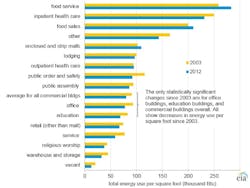
Figure 1. Some typical source and site EUI’s for various building types, as listed in the Commercial Building Energy Consumption Survey (CBECS), reported by the U.S. Energy Information Administration (EIA). These represent national building median energy use, in kBtu/sqft-yr.
With information like this, a building’s site EUI can be considered similar to a car’s “miles per gallon” (MPG) rating, used to label the efficiency or economy of an automobile when compared to another. It allows one to relate total yearly gas and electricity use to industry standards, which can help in recognizing if the facility is 'on' or 'off' the energy mark when compared to others. In addition, once target areas of excess energy consumption are identified, it provides a useful tool in helping assess potential energy and utility cost savings based on estimates of improving efficiency resulting from proposed energy reduction measures.
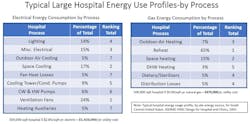
Food service, inpatient health care (hospitals), and food sales buildings are the most intensive users of total energy among the building types. Hospital HVAC energy use is high because of around-the-clock demand for all end uses and because of a wide variety of specialized, energy-intensive equipment, such as medical imaging equipment. Large, single-source energy consumers include reheat, which alone may account for 40% or more of a hospital's natural gas consumption, while ventilation fans can consume up to 25% of its total electrical use.
Figure 2. Hospital energy usage profiles.
New hospitals can reduce energy consumption from the onset of design with a comprehensive approach that includes maximizing the building envelope, utilizing heat recovery systems, optimizing space usage, and implementing renewable energy sources. But what about legacy hospitals that struggle to overcome operational issues resulting from buildings in need of updating and equipment which may have been poorly kept or is nearing the end of its service life? While there are many ways to improve upon the efficiency and sustainability of any HVAC system, here are two relatively straightforward and effective measures.
Improve Chiller Plant Delta-T
Within an HVAC system, chilled plants may typically be the largest hospital energy users and have the highest first cost, so optimizing their operation makes good overall financial sense. Chiller central plant systems are designed with a (building side) supply and return water temperature difference, also called delta-T (∆T). This specified chilled water (CW) temperature rise is what drives the thermal heat transfer between the water circulated through piping, and the room terminal units or air handling unit (AHU) coils that provide air conditioning for the building.
Design water ∆-Ts can range from 10°F to 20°F or more. But regardless, once the system is designed and the chiller is selected and manufactured for its specified ∆T, if anything less is delivered in operation (low ∆T), it can result in reduced performance (capacity) that may lead to inadequate temperature control such as a space that is too hot, too humid, or both. Many times a facility manager may incorrectly assume their central plant is lacking capacity and might consider the purchase of an additional chiller. But, in fact, the plant is not performing at design capacity due to what has been labeled in the industry as “low ∆T syndrome”, as described above.
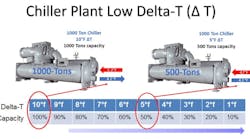
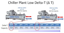
Figure 3. A 1000-ton chiller designed for a 10°F ∆T but experiencing a 5°F∆T will run at 50% capacity, producing only 500-tons.
A simple example would be a chilled water plant designed with two 1000-ton chillers sized to manage a peak building load of 2000-tons. With this design, both chillers would run to meet full load requirements. Assuming these chillers are selected for 42°F supply/52°F return water (10°F ΔT), then each chiller should be capable of producing 1000-tons when processing the full CW design ΔT at design flow. If the building load is reduced to 50% and the CW system can maintain the 10°F ΔT with reduced flow (assuming pump VFDs), then one chiller could be run at 1000-tons (100% capacity) while the other chiller along with any ancillary devices could be shut off. This sequence can help optimize the energy efficiency of the HVAC systems design.
On the other hand, if the CW system is capable of merely producing a 5°F ΔT, then each chiller would produce only 50% of its full load capability, or 500-tons (see diagram). In this example, both chillers (along with its associated chilled and condenser water pumps and cooling tower) would need to run to meet the 1000-ton (50%) building load. You can easily comprehend the inefficiencies and other issues that arise with a CW plant running in this condition, including lack of cooling capacity, chiller sequencing complexity and excess energy consumption.
There are various reasons low ∆T can occur, and its influence is notoriously present in large campus-type CW systems. The cause and effect of this problem occurs anytime there is an unwarranted reduction in a terminal unit or cooling coils thermal heat transfer performance, or the ability of the system to “wring-out” all the btu’s the chilled water has to offer. This can result in system controls (and often building engineers) compensating for a loss in HVAC system capacity by speeding up fans, lowering chilled water temperatures and increasing chilled water flow, all at the expense of reduced system capacity and increased energy use. When heat transfer devices can be restored to their design operating performance, some of these energy inefficiencies may be reversed or avoided.
One of the most effective ways to help correct chiller low delta-T syndrome is improve the transfer of btu’s through terminal units or AHU coils. Some possible items to look at in helping diagnosed this problem within your CW central plant should include:
- What is the “operating” CW ΔT, and is it on target with the original design?
- Are you pumping the proper CW system flows (gpm)?
- Are space temperature set-points too low? If yes, are fully open CW valves incapable of satisfying the space temp. set point?
- Are space and system temperature sensors properly installed and calibrated?
- Do your AHUs have dirty filters?
- Are your AHU cooling coils dirty? (See below.)
- Are your AHU cooling coils improperly piped?
- Are space terminal units fouled and dirty?
- Is there air in the piping system?
- Does your CW system include any 3-way control valves?
- Are you using pressure-independent control valves (PICV) at terminal units and coils? (If not, you should be).
Keep Cooling Coils Free of Microbial Growth
As described above, a reduction in a cooing coils thermal performance can occur when its surface accumulates anything that insulates heat transfer, such as bacteria, mold, and biofilm. A recognized method to help remove accumulated bio-growth from cooling coils is with steam or chemical cleaning treatment, a physical process that may be both interruptive (system downtime) and labor-intensive. While effective if done correctly, it must be repeated on a regular basis (typically annually) as bio-contaminants can proliferate again shortly after treatment.
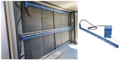
Figure 4. Needlepoint Bipolar Ionization installed on upstream side of cooling coil to reduce microbial growth
Beyond physical cleaning methods, proven technologies may be employed that can work around the clock to help effectively keep coil surfaces continuously clean, without disruption. Two technologies, in particular, Ultraviolet Disinfection (UV-C) lamps and Needlepoint Bipolar Ionization (NPBI), both have a long history of satisfactory results. While both actually consume electricity, they can help return coil pressure drop and heat transfer efficiency to original design conditions, providing documented AHU operational cost savings and energy reductions of between 10 and 25%.
An added advantage beyond energy savings alone comes from providing a higher quality of delivered air to the occupied environment, contributing significantly to better overall indoor air quality (IAQ) and a healthier hospital for patients and staff.
Dependent on the type of source energy being used by the hospital, it will typically have an associated release of greenhouse gas emissions tied to its production and delivery. By improving the facilities site EUI, through energy saving measures such as those described above, healthcare organizations can take advantage of both utility cost savings, as well as reductions in GHG emissions reflected through lowering consumption of the source energy itself.
Any new sustainability plan should start with an assessment of the facility’s energy needs, its consumption, and areas of potential waste. Then look at implementing cost-effective energy management measures that can help reduce all three.
About the author
David Schurk is Director of Healthcare Vertical Markets for GPS Air (formerly Global Plasma Solutions), Charlotte, NC. An ASHRAE Distinguished Lecturer, he is a Licensed Designer of Engineering Systems with over 40-years of experience in design and analysis of HVAC and air cleaning systems for multiple markets. His focus is on aerospace and healthcare facilities. Email: DSchurk@gpsair.com.


