Dynamics of Tall-Building Riser Design, Part 1 of 2
Though we have figured out how to build strong tall structures and safely move people inside, challenges of heating and cooling, of moving fresh water in and dirty water out, and of providing fire protection and electricity persist. These are made all the more complicated by a need to defy gravity. This article discusses basics of pipe-riser design and performance, identifies key considerations regarding the use of expansion joints in pipe risers, and explains codes and standards governing the guidance and support of risers.
Thermal-Expansion Basics
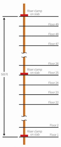
Consider the riser pipe in Figure 1. It runs the entire height of the building, 50 stories. With a slab-to-slab height of 10 ft, the pipe is 500 ft tall. A typical support for such a pipe is the riser clamp, installed maybe on every other floor. With no temperature change, the weight of the riser is distributed evenly between the riser clamps.
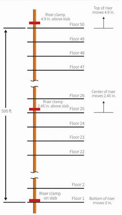
When water in the pipe is heated (Figure 2), the pipe expands against the riser clamps. Movement of the riser clamps, however, is restricted in only one direction, down. There are no restrictions to upward movement; the clamps will just move up with the pipe. Any clamp above the bottom floor will float above the slab. All of the weight of the pipe, the insulation, and the media will be on the bottom clamp. Few pipe clamps are designed to support the full weight of a tall riser.
One solution involves installation of a pipe anchor designed to support the full weight of the riser at the bottom of the riser. But let’s look at how much the pipe moves. Let’s say our pipe is made of steel, and the liquid medium is 180°F water. If we assume an ambient temperature of 50°F, the pipe will want to expand according to the equation:
∆L = ∝L0∆T
where:
∆L = length change (inches)
∝ = coefficient of thermal expansion (for steel, 6.33 × 10⁻⁶ in./in./°F)
L0= starting length (6,000 in.)
∆T = temperature change (180°F − 50°F = 130°F)
∆L= 4.9 in.
The very top of the riser will move up 4.9 in. Is that a problem? It could be. Can the takeoffs at the upper levels move about 5 in. without breaking? Maybe, if there is enough runout to the equipment connections. Will the field conditions allow the pipe to move this much without colliding with structure or equipment? Maybe, but, usually, such a question cannot be answered until a structure is up and pipes are installed.
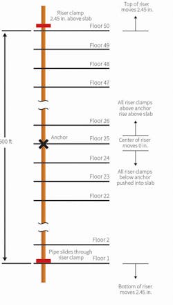
One solution may be to move the anchor to the center of the riser (Figure 3). The anchor is a hard connection from the pipe to the structure and a point of zero movement. Now, the riser is divided into two sections, each 250 ft, and the maximum movement of the pipe is half of the entire riser, or 2.45 in. If the previous questions concerning the takeoffs at the upper levels and field conditions can be answered during design with 2.45 in. of movement, great—on to the next project!
But wait. What about those riser clamps? Above the anchor, they will ride on the pipe, rising above the floors. Below the anchor, they will try to keep the pipe from moving downward. The likely outcome will be the clamps slipping along the pipe as it moves. If the riser clamps are welded to the pipe, something—the clamp or the pipe—will break. With any luck, it will be the clamp, but, then, the anchor will be carrying the load of the entire riser.
Riser Spring Supports
What about spring supports, systems of anchors, guides, and supports for risers designed to move with pipe? Spring supports stay in contact with floor slabs as pipe moves. As pipe moves, the springs stretch or compress to exert more force on a floor slab, which takes load off of the main anchor in the center of the riser. These systems are effective in taking load off of main anchors; however, they have limitations:
- Pipe still moves. Nothing can prevent this. In the example of our 500-ft riser, the anchor would be in the center, and the ends would move the same 2.45 in.
- Only one anchor is permitted in a riser. A second anchor would restrict pipe movement, resulting in tremendous forces in the anchors and floor slabs and potentially significant stresses in the pipe.
- Whether this type of system can be adapted to copper risers is unclear. Available manufacturers’ literature does not specifically mention copper as an acceptable pipe material for these support systems.
Use of riser clamps or spring supports results in limited control of pipe movement. Expansion joints allow for better control of pipe movement. Before looking at expansion joints, however, let’s consider what happens to the internal pressure of a riser.
Pressure and the Height of a Water Column
Internal pressure along the axis of a horizontal pipe generally varies by a small amount. As the pipe is tipped up, pressure in a fluid-filled riser builds. Because of the weight of water, the pressure at the bottom can be significantly higher than that at the top.
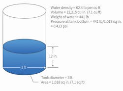
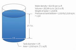
Consider a tank holding 1 ft of water (Figure 4). No matter how full, a tank experiences the most force at the bottom. Each inch of water added increases the weight the bottom of a tank must hold. When the height of water reaches 27.7 in., there is 1 lb of force per square inch at the bottom of a tank (Figure 5).
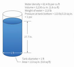
The narrower the tank, the lesser the water needed to fill to 27.7 in. Although the bottom of a narrower tank has a smaller area, the force on each square inch still is 1 lb (Figure 6).
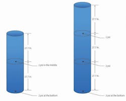
For every 27.7 in. of water column, the pressure at the bottom of a tank increases by 1 psi (Figure 7). For every 12-in. section of water, pressure increases by 0.43 psi. Using this logic, the pressure at the bottom of our 500-ft riser is:
pressure = 500 ft × 0.43 psi per ft = 215 psi
This is referred to as hydrostatic pressure. It is why hydronic equipment seldom is located in the basement of tall buildings and why very tall buildings have risers that are subdivided between intermediate mechanical-equipment rooms. With steam, gas, and air, column height is not an issue because of the much lower densities of the substances.
Next month, Part 2 of this article will discuss riser structural-stability considerations, pipe guides, bellows expansion joints, flexible hose and braid loop expansion joints, and more.
Marty Rogin, PE, is engineering manager for The Metraflex Co. His 29 years in the field have taken him from the edge of space down to the bedrock of our infrastructure systems and several interesting places in between. He is a licensed professional engineer in 13 states and has degrees in engineering mechanics and aerospace engineering.
Did you find this article useful? Send comments and suggestions to Executive Editor Scott Arnold at [email protected].

