By KENNETH M. ELOVITZ, P.E., Esq.
After an engineer calculates heating and cooling loads and designs ductwork to bring supply air to a room, one of the next steps is to select supply air outlets. Whether floor outlets, sidewall grilles, or ceiling diffusers, the key engineering parameters for selecting registers, grilles, and diffusers are air distribution performance (as measured by Air Diffusion Performance Index/ADPI) and noise.
1) Use manufacturers' cataloged outlet throw to achieve high ADPI.
ADPI (air diffusion performance index) is a combined measure of air velocity and temperature uniformity in the occupied zone of a room. The 2019 ASHRAE Handbook - Applications page 58.1 defines the occupied zone is the part of the room where people are likely to be, generally from the floor up to a height of 6 feet.
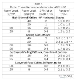
ADPI ranges from 0 to 100. Designers can use the outlet throw ranges in Tables 6A and 6B in Chapter 58 of the 2019 ASHRAE Handbook - Applications to select supply outlets to achieve ADPI of at least 80. Table 1 (below) reproduces selected data from the ASHRAE tables for combined heating and cooling duty:
The ASHRAE guidelines are expressed as throw (T50) divided by characteristic length (L). The characteristic length is the distance from the outlet to the opposite wall or to the midpoint between adjacent outlets. Manufacturers' catalogs list outlet throw in feet by outlet size and CFM to three distances: 150, 100, and 50 fpm terminal velocity of the air jet leaving the device. To use the ASHRAE table recommendations, divide published throw in feet by characteristic length (also in feet).
For example, a 12-in. x 15-in. office has a design supply air flow of 120 CFM. To use a 4‑way blow, square perforated face diffuser in the center of the room, the throw to 50 fpm terminal velocity should be between 12 and 18 feet (2.1 x 6 and 3.2 x 6). A 2-way corner blow outlet in one corner of the room with throw between 25 and 38 feet (2.1 x 12, and 3.2 x 12) would also work.
Throw that is too short results in too much air in some parts of the room (drafts due to dumping) and not enough in others (stagnant areas). Throw that is too long result in drafts due to air jets bouncing off walls or colliding with adjacent air jets. Manufacturers' throw data are for isothermal jets. Throw from overhead devices changes by about 1% per degree F difference between room air and supply air temperature, decreasing for cooling and increasing for heating.
2) When selecting outlets, match the outlet shape and throw pattern to the shape of the room.
Long, narrow rooms can use one way blow outlets at one end of the room or 2-way blow outlets in the center. A 4-way blow square outlet in the center of the room selected for the short dimension would leave stagnant areas at the ends of the room. It might be possible to find a 4-way blow rectangular outlet that has appropriate throws in both the long and short dimensions. An imaginary dividing line across the width of a 2-x-1 room that creates 2 nearly square rooms could be served by two 4-way blow square outlets, one in the center of each square.
Especially in small rooms, the lighting designer and the sprinkler engineer often want to locate their systems and equipment in the center of the room. Choosing HVAC outlets that avoid the center of the room can ease coordination.
3) Noise is the other key parameter for selecting registers, grilles, and diffusers.
Generally speaking, the HVAC system should not be the loudest sound in the room. Return and exhaust inlets can be selected based on maximum face velocity. 250 fpm to 275 fpm is a good guideline for very quiet applications like residences, hotel rooms, and theaters. For process exhaust, noise is important, but function is more important. Therefore, select process exhaust inlets based on required capture velocity even if noise might result.
Select supply air outlets based on neck velocity and manufacturers' catalog NC ratings. Neck velocity under 500 fpm is often a good starting point for quiet selections.
Catalog NC ratings are for individual devices with ideal entry conditions and include a fixed room attenuation effect (usually 10 dB). Two devices in the same room will double the noise: a 3 dB increase; 4 devices means a 6 dB increase. Dampers, elbows, or squashed flex duct that create uneven airflow in the diffuser neck will also increase noise. If the actual room effect is less than 10 dB, the diffuser or grille will be louder than the catalog rating. Erring on the side of quieter selections allows for field conditions that increase unwanted noise.
4) Calculate carefully.
When calculating pressure drop for return or exhaust systems, remember to include 1 velocity head to accelerate still air in the room to duct velocity. Loss coefficients for hoods, grilles, and fittings are friction losses and do not include the energy to accelerate air to duct velocity.
5) Watch for short circuiting.
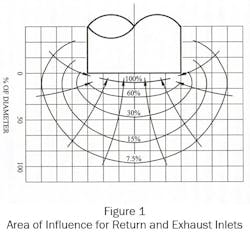
Return/exhaust air inlet location is more flexible than supply outlet location because throw or area of influence is not a factor, especially if face velocity is kept low for quiet operation. Figure 1[1] shows that the velocity near an exhaust inlet decays to less than 10% of the face velocity within 1 duct diameter of the inlet.
Consider an example to illustrate that return air inlet location does not affect a large area of the room. Suppose a 12' x 15' office has a design supply air flow of 120 CFM and a 6" x 10" eggcrate return air grille. The face velocity at the eggcrate is 288 ft/minute. The inlet stream velocity decays to 30 ft/minute or about the same as general room air velocity within 1 duct diameter or 8½ inches of the inlet.
At the same time, short circuiting can occur, especially if the return air inlet is within the 150 ft/minute or 100 ft/minute throw envelope from the supply outlet.
The risk of short circuiting increases with heating supply air, which tends to hang near the ceiling if the supply air temperature is more than 95F to 105F. Warm air recirculating into the return air inlet raises the heating coil (or furnace) entering air temperature, further raising the supply air temperature, making stratification even worse. Some designers solve the problem with low return inlets, especially in high ceiling residential spaces like open stairwells.
While a low return is not always necessary when heating from overhead, it does help combat stratification. Figure 1 shows that the area of influence of the return air inlet is too small to "pull the warm air down". However, each cubic foot of return air that enters the inlet from the lower part of the space is replaced by air from the upper regions, so low returns can discourage stratification and encourage mixing.
Register, grille, and diffuser selection affects indoor environmental quality, temperature and velocity uniformity and noise. Making workable selections offers a lot of flexibility and does not have to be complicated.
##########
[1] American Conference of Governmental Industrial Hygienists (ACGIH), Industrial Ventilation, 23rd Edition, 1998, page 3-7, available at https://archive.org/details/gov.law.acgih.manual.1998/mode/2up.
##########
A member of the HPAC Engineering Editorial Advisory Board, the author is both a mechanical and electrical engineer, as well as in-house counsel for Energy Economics, Inc., a consulting firm based in Foxboro MA. Email him at [email protected].
