Fan-Efficiency Metrics
Editor’s note: This article previously was published as “FANtastic! A Closer Look at Fan Efficiency Metrics” in Volume 43-3 of Trane’s Engineers Newsletter in October 2014. It was edited here for length and style.
Air Movement and Control Association (AMCA) International estimates fans account for 30 to 40 percent of commercial-building HVAC energy consumption.1 Improving fan efficiency, therefore, is an important step toward reducing global, overall energy use.
Better understanding of the usefulness and limitations of each fan-efficiency metric requires explanation of some terminology.
Application-dependent vs. application-independent. Fan-efficiency metrics can be broadly characterized based on whether they consider a fan’s operating point:
- An application-dependent efficiency metric considers a fan’s actual operating point.
- An application-independent efficiency metric does not consider a fan’s actual operating point.
As we will see, some metrics function better as one dependency type over the other.
Product efficiency vs. system efficiency. Fan-efficiency metrics also can be characterized based on whether they consider a fan alone or the overall system:
- Product efficiency: The efficiency metric considers the fan alone.
- System efficiency: The efficiency metric considers the overall system, including fan-system effects, duct leakage, and duct design.
Even if a fan has a high peak efficiency, how that fan is applied in a system ultimately will determine how much energy is used. The impact of a system on fan energy use heavily outweighs the impact of a fan alone.
Total pressure vs. static pressure. Fan-efficiency metrics tend to be defined in terms of fan total pressure, the total pressure (static pressure plus velocity pressure) at the fan outlet minus the total pressure at the fan inlet. Fan total pressure is a measure of the total mechanical energy added to the air by a fan.
By definition, static pressure is the total pressure at the fan outlet minus the total pressure at the fan inlet minus the velocity pressure at the fan outlet. This can be a source of confusion. When a fan inlet is unducted, inlet velocity pressure is zero and total pressure equals static pressure. When a fan inlet is ducted, care must be taken to measure the total pressure at the inlet, rather than just the static pressure. When an outlet is unducted, outlet velocity pressure is zero, in which case a change in fan total pressure will equal a change in fan static pressure.
With ducted systems, to ensure all forms of energy are accounted for, consider total pressure. Note that many engineers design systems using only static pressure. They account for any velocity-pressure changes and, therefore, total-pressure changes by ensuring the duct connection to the fan matches the intent (e.g., three duct diameters of straight duct sized the same as the fan outlet) and by using dynamic-loss coefficients (“Kt” factors).
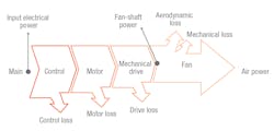
Extended product (i.e., wire to gas). The metrics discussed in this article tend to address only the power applied to the fan shaft. AMCA soon will release AMCA Publication 207, Fan System Efficiency and Fan System Input Power Calculation, which will provide guidance, a method, and tabulated data for calculating fan-system input power and overall efficiency of a complete fan system (Figure 1). This will include fan, electric-motor, and, if applicable, power-transmission and/or motor-controller efficiency.
Although direct measurement of input power is preferred, AMCA Publication 207 at least will provide a common basis for calculation and comparison.
The Air-Conditioning, Heating, and Refrigeration Institute (AHRI) recently took another important step toward accurate, calculated system input power with the publication of ANSI/AHRI 1210, Performance Rating of Variable Frequency Drives. This standard provides a uniform method of measuring and comparing variable-frequency drives by establishing testing and rating requirements.
Fan-Efficiency Grade (FEG)
Many of the latest energy codes and standards, including the International Green Construction Code and ANSI/ASHRAE/IES Standard 90.1-2013, Energy Standard for Buildings Except Low-Rise Residential Buildings, reference a fan-efficiency classification system known as fan-efficiency grade (FEG). FEG was defined with the publication of ANSI/AMCA Standard 205, Energy Efficiency Classification for Fans, in 2010. It is by far the most commonly applied fan-efficiency metric today.
(Note: Fan-motor efficiency grade [FMEG] is a version of FEG incorporating input power. It is not widely used in the United States, where fans often are sold separately from motors and/or motor controllers, but it is an important metric in the European Union, where fan-motor-drive combinations are more common.)
The first question we must ask is why can we not use the simpler fan-efficiency calculation. Let’s look at the impact of fan diameter on efficiency.
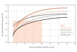
Larger fans vs. smaller fans. Increased turbulence and tolerance magnification result in smaller fans operating at reduced efficiencies compared with larger fans. As shown in Figure 2, this change can be rather dramatic as diameter increases—even for the same type of fan. Consider the area in the shaded box. A single-number efficiency limit (e.g., greater than 65 percent) would either effectively eliminate the use of smaller-diameter fans or require a limit so lenient (e.g., greater than 45 percent) it would have little impact on efforts to reduce building energy use.
FEG solves the small-fan dilemma by accounting for the impact diameter has on efficiency.
FEG alone is an application-independent metric, based on the peak aerodynamic efficiency of a ducted fan separate from its motor and drive. It is important to note, however, that a fan’s peak aerodynamic efficiency ultimately will not determine how much energy is used. Even a highly efficient fan could be selected to operate at a point far from this peak efficiency.
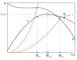
Accompanied by an allowable selection range, or “window”—accomplished by defining a number of percentage points from peak efficiency, as shown in Figure 3—FEG can be used as an application-dependent metric. Keep in mind the selection window is in terms of percentage points, not a percentage. For example, if the peak efficiency is 70 percent, a 15-point window means the fan must be selected with an efficiency of at least 55 percent (not 0.85 × 70% = 59.5%).
Because FEG ratings are an indicator of peak fan efficiency, not actual operating efficiency, their main value is in segregating fans during selection. Once an engineer has narrowed a list of available fans to those meeting a minimum FEG rating—and has filtered those outside of the allowable selection window—his or her focus should turn to other selection parameters, such as actual power consumed, sound-power levels, size, and cost.
AMCA Publication 206, Fan Efficiency Grade Application Guide, provides an overview of issues associated with fan energy consumption and offers guidance for using FEG in codes, standards, and regulations as a means to increase the use of energy-efficient fans.
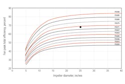
Determining FEG classification. Determining FEG classification does not require calculation, but, rather, comparison of a fan’s peak aerodynamic efficiency based on total pressure to a chart in ANSI/AMCA Standard 205. For example, consider a 25-in.-diameter fan with a peak total efficiency of 68 percent. Using the chart in Figure 4, we can see 68 percent falls between the FEG71 and FEG75 curves. This fan, then, would be labeled FEG71.
By definition, a FEG label is assigned based on fan-component performance data in accordance with a standard such as ANSI/AMCA Standard 210/ANSI/ASHRAE Standard 51, Laboratory Methods of Testing Fans for Certified Aerodynamic Performance Rating. If an equipment-mounted fan is being evaluated (see sidebar “Equipment-Mounted Fans”), the manufacturer will need to provide two data sets: one for fan-component performance and one for equipment performance. The former is used to determine whether a given operating point would meet an application-independent FEG selection window, while the latter is used to provide in-situ performance data.
Note the shape of these curves generally is intended to ensure an entire product line of geometrically similar fans can meet the same FEG. However, several factors could cause some diameters or variations to have different FEG labels.
With FEG classification determined by the fan manufacturer, the system designer needs only to filter available fan selections by the minimum FEG level prescribed by the appropriate code or standard. As discussed earlier, the designer then is expected to determine whether the desired fan operating point meets the allowable selection-window requirement.
How FEG differs from the ANSI/ASHRAE/IES Standard 90.1 fan-power limitation. The fan-power limitation in ANSI/ASHRAE/IES Standard 90.1 is an overall system design limitation, not a requirement of the fan as a component. There are many examples of equipment, such as those listed in Section 6.4.1.1 of the standard, or components, such as motors, that contribute to overall system power while still having a separate limitation.
To meet the requirements of ANSI/ASHRAE/IES Standard 90.1, a system designer should consider only fans that meet application-independent (FEG level) and application-dependent (allowable selection window) requirements. If the fan-power limitation still cannot be met, the entire system needs to be analyzed to reduce fan power.
Shortcomings. FEG is an elegant metric that solves the small-diameter dilemma and provides a simple classification system for segregating fans based on peak aerodynamic efficiency. However, it is not without limitations:
- FEG is best suited for ducted applications. The application-dependent selection region often eliminates fans in unducted or low-pressure applications from consideration. Even lower-pressure applications, such as return or exhaust fans, suffer, as the minimum FEG limit forces the use of larger-diameter fans or a different fan type altogether (e.g., an axial fan in lieu of a centrifugal fan). This can make retrofits more expensive and difficult. Keep in mind: These lower-pressure fans typically use less energy than their supply counterparts.
- The requirement that total pressure and total efficiency be used complicates the selection of unducted fans. Fan static pressure is the only useful work in an unducted application, but FEG requires the use of total pressure. As a result, artificial outlet areas must be defined in an attempt to quantify energy that ultimately is unused.
Within the fan community, a metric that could address some, if not all, of these shortcomings is being considered.
Performance-Based Efficiency Requirement (PBER)
That metric is performance-based efficiency requirement, or PBER (sometimes referred to as fan-efficiency ratio, or FER). Formulated to address the unducted or low-pressure-fan dilemma, PBER yields a minimum required efficiency based on the useful work performed at a given operating point (airflow and pressure). Alternatively, maximum power in lieu of a minimum efficiency could be output. This type of metric would continue to allow fans with lower peak efficiencies, or fans selected at an inefficient operating point, to be used as long as their energy use remained relatively low.
Calculating PBER. The calculation procedure for PBER is a little more complicated than that for FEG. We start with a target efficiency, applying a series of factors to adjust it for operating points at which actual energy use is relatively low:
required efficiency = target efficiency × flow factor × pressure factor
where:
target efficiency = the minimum peak aerodynamic efficiency allowed. (Note: The required efficiency of the fan never will exceed this target efficiency.)
flow factor = an adjustment to reduce target efficiency for a fan operating at lower airflows. (Note: FEG has an implicit flow factor, which is how smaller-diameter fans are handled.)
pressure factor = an adjustment to reduce target efficiency for a fan operating at lower pressures. (Note: Unlike FEG, PBER considers the pressure capability of a fan.)
The choice of pressure is dependent on whether a fan is ducted or unducted:
- For ducted fans, use total pressure.
- For unducted fans, use static pressure.
The formula is the same regardless of pressure type; only the constants change. For example, target efficiency could be 66 percent for ducted fans and 60 percent for unducted fans.
Let’s consider a PBER calculation for an unducted fan. First, we need to assume flow and pressure factors:
required efficiency = 60% × (cfm ÷ [250 + cfm]) × (P ÷ [0.40 + P])
The 60 percent, 250, and 0.40 values are for illustrative purposes only. Code bodies may use different values. The 250 value in particular was chosen to closely approximate the implicit FEG flow factor.
Assuming 10,000 cfm and 3.0-in. H2O static pressure, the required static efficiency for an unducted fan would be:
required efficiency = 60% × (10,000 ÷ [250 + 10,000]) × (3 ÷ [0.40 + 3]) = 52%
In this case, any unducted fan with a static efficiency of 52 percent or more at this operating point would be accepted.
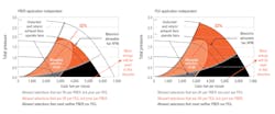
PBER compared to FEG. As fans become more efficient, the shape of the allowable PBER selection region more closely matches the shape of the allowable FEG selection region. Consider the two fans illustrated in Figure 5. The region bounded by the dashed black line (surge region), the dashed gray line (peak efficiency − 15 points), and the solid black line (maximum revolutions per minute) is the allowable FEG selection region. The region bounded by the orange solid line is the allowable PBER region. The two regions are quite dissimilar for the inefficient fan, but very similar for the more efficient one. Thus, the metrics allow similar operating points for highly efficient fans. But unlike FEG, PBER does not actually eliminate any fan from consideration; instead, it reduces the valid operating region for less efficient fans.
How can PBER be used as an application-independent metric, and would an application-independent PBER still provide advantages over FEG?
One option is to determine input airflow and pressure based on a known intersection (e.g., peak aerodynamic efficiency and maximum cataloged fan speed). This calculation is not the system designer’s responsibility. It can be used to determine maximum allowable fan speed, which the designer can compare to operating revolutions per minute.
As illustrated in Figure 6, a maximum allowable revolutions per minute permits selections outside of the PBER range, but, unlike FEG, significantly reduces the operating points at which a fan consumes the greatest amount of energy.
Note that PBER, also unlike FEG, closes any loopholes associated with a steep efficiency curve. Typical of axial fans in particular, a steep efficiency curve is one whereby a fan may have a very high peak efficiency, but low operating off-peak efficiency.
A metric like PBER maximizes energy efficiency by considering selection point or trimming the most energy-intensive regions off of a fan’s valid selection window. Additionally, by considering actual input power as a factor, it allows alternative fan types, such as forward-curved (FC) fans, to be used, even if they may have a lower peak efficiency (see sidebar “Forward-Curved [FC] Fans”). The alternative for FC fans is to assign a unique FEG limit. However, this does not prevent a FC fan from being used in an inappropriate, high-energy-use application. The same can be said for return/exhaust fans. The PBER approach requires supply-fan selections to be more efficient than return/exhaust-fan selections.
Current Requirements
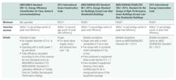
Table 1 details the latest fan-efficiency requirements in published codes, standards, and publications.
(Note: As mentioned previously, the selection window is in terms of percentage points, not a percentage. Peak total efficiency is based on component performance data. For evaluation of an equipment-mounted fan, care must be taken to ensure the correct data set is being used.)
Component fans now can be certified in accordance with AMCA Publication 211, Certified Ratings Program — Product Rating Manual for Fan Air Performance, as a FEG-rated fan and carry a specific label. To date, this is the only certification program for component-fan energy efficiency.
Products Affected
Based on the requirements in Table 1, the following exceptions are common:
- Fans that are part of equipment listed in Section 6.4.1.1 of ANSI/ASHRAE/IES Standard 90.1.
- Fans in equipment packages that are third-party-certified for air or energy performance.
Section 6.4.1.1 of ANSI/ASHRAE/IES Standard 90.1 addresses the following equipment containing fans: direct-expansion air conditioners (packaged rooftop units, split systems, and self-contained units), air-cooled condensing units, water-source heat pumps, air-cooled chillers, packaged terminal air conditioners, furnaces, cooling towers, and variable-refrigerant-flow systems. The fans in these products, then, are exempt from having to also meet minimum FEG and selection-window limitations.
Most air-handling products bear a “third-party-certified seal” from AHRI. Catalogued air handlers and blower coils are certified to ANSI/AHRI Standard 430, Central Station Air-Handing Units, which evaluates air handlers on the basis of airflow, static pressure, fan speed, and brake horsepower. Likewise, fan-coils and unit ventilators are certified to ANSI/AHRI 440, Performance Rating of Room Fan-Coils. Therefore, the fans in these products are exempt from having to also meet minimum FEG and selection-window limitations.
Custom air-handling units typically do not carry an AHRI seal. Most custom-air-handling-unit manufacturers, however, incorporate fans certified in accordance with AMCA Publication 211 into their equipment, and it is likely the fans carry the new FEG seal.
Looking Ahead
FEG and metrics such as PBER certainly are a step in the right direction. But where will the industry go from here?
Considering the substantial amount of energy that can be saved at part load, a metric encouraging speed control (e.g., variable-frequency drives) would make sense. Regulation activity for other components (pumps, in particular) seems to suggest such a metric might be forthcoming. Similarly, a metric to account for efficiency at part-load operation would be beneficial. Endeavors such as AMCA Publication 207 and ANSI/AHRI 1210 are helping to get us there.
Direct-drive fans are becoming more and more prominent. Having a way to encourage their use would make sense. For example, PBER could include a drive factor (in addition to the existing flow and pressure factors) to encourage the use of direct-drive fans. The drive factor also could provide a method of incorporating a wire-to-gas consideration.
Other changes to fan-efficiency regulations could include:
- The raising of the minimum FEG.
- The narrowing of the allowable selection window.
- The elimination or reduction of some exceptions.
- The assignment of different FEG requirements for different fan types.
- The switch from FEG to PBER or a combination of the two.
Whatever the future holds, it is obvious fan efficiency will continue to be a critical design parameter for system engineers.
Reference
1) Smith, W. (2014, Summer). 2012 fan market data defines the path to higher efficiency. AMCA inmotion, pp. 22-29.
Dustin Meredith, PE, is an applications engineer specializing in acoustics and fans for Trane. He is Trane’s primary voting representative for Air Movement and Control Association International; the chair of ASHRAE Technical Committee (TC) 2.6, Sound & Vibration Control; and a corresponding member of ASHRAE TC 5.1, Fans. Jeanne Harshaw is a program manager in Trane’s Systems and Applications Engineering group. Her primary responsibility is development of educational resources and programs.
Did you find this article useful? Send comments and suggestions to Executive Editor Scott Arnold at [email protected].
SIDEBAR: Equipment-Mounted Fans
Test and rating standards are created to ensure uniformity among manufacturers and, thus, afford system designers and equipment manufacturers consistent data for evaluation. ANSI/AMCA Standard 210/ANSI/ASHRAE Standard 51, Laboratory Methods of Testing Fans for Certified Aerodynamic Performance Rating, was created for fans used as stand-alone components and undoubtedly is the industry standard for fan airflow performance.
Once a fan is installed in a cabinet (such as that of an air-handling unit), its performance can be influenced by a number of factors. Known generally as “system effects,” these factors can be approximated, but combinations must be tested. Common “system effects” include:
- Cabinet proximity.
- Component (coils, filters, internal control enclosures, etc.) proximity.
- Motor proximity.
- Bearings, sheaves, and other drive components.
- Discharge orientation.
Equipment test and rating standards include these effects. One such standard is AHRI 430, Performance Rating of Central Station Air-Handling Unit Supply Fans. An equipment standard will provide the most accurate estimate of final in-situ performance. In the absence of an equipment standard, a fan that has been tested and rated in accordance with ANSI/AMCA Standard 210/ANSI/ASHRAE Standard 51, coupled with any appropriate system effects (see AMCA Publication 201, Fans and Systems), should be used.
A cabinet’s effect on a fan can be quite significant. Addressing this and other effects can have as much, if not more, influence on overall energy use as addressing fan efficiency itself. By considering the equipment a fan is mounted in, additional energy savings can be realized.
SIDEBAR: Forward-Curved (FC) Fans
- As a lower-cost, less-efficient option for an application calling for a more-expensive, more-efficient airfoil (AF) fan.
- For their unique characteristics, as described below.
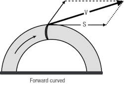
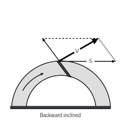
AF and BI fans are most efficient when selected close to the surge region. Moving toward the surge region along a constant-speed (revolutions per minute) curve, the severity of stall is gradual for FC fans. Therefore, they can be operated at peak efficiency with less concern about crossing into the surge region.
Consider that some products simply are selected from a catalog, with little known about their system resistance. Additionally, the user might not be particularly experienced in fan selection. If he or she were to select the more efficient fan with an appropriate safety factor, the fan could end up not being as efficient as the more-tolerant FC fan.
Advantages of FC fans over other housed fan types include:
- FC fans have a relatively flat acoustical spectrum without an objectionable blade tone. They are particularly suited for lower-pressure applications whereby they are in close proximity to occupied spaces.
- FC fans are most efficient at low pressure. They are particularly suited for lower-static supply-fan applications and return- and exhaust-fan applications.
- FC fans are compact, often resulting in a smaller unit footprint.
- FC fans typically operate at a lower number of revolutions per minute, which improves bearing life and results in higher reliability.
- FC fans are very forgiving. The onset of objectionable stall is very subtle. Additionally, the fans can be operated at much lower airflows.
- FC fans are overloading, meaning input power naturally decreases as system pressure increases (filter loading).
- FC fans are easier to assemble and install; the inlet-cone/impeller gap is not critical.
Drawbacks of FC fans compared with other housed fan types include:
- FC fans have a lower peak efficiency than BI or AF fans.
- FC fans have lower static-pressure capacity generally because of structural limitations.
- With FC fans, low-frequency noise is higher than it is with BI and AF fans.
- The relatively flat cfm-vs.-pressure curve of FC fans causes larger changes in airflow rate when system pressure changes.
- FC fans are overloading, meaning input power increases as flow increases and system pressure decreases (filter changeout).

