Since the days of the early Greeks, Romans, and Chinese, when, archaeologists believe, ice and snow was stored in caves for use during warm weather,1 man has been practicing thermal-energy storage (TES).
TES is achieved through two mechanisms: sensible-energy storage and latent-energy storage. Sensible-energy storage is accomplished by decreasing the temperature of the stored medium. Latent-energy storage is accomplished by changing the phase of the stored medium. For facility- and process-cooling applications today, three main types of TES are employed:
- Chilled-water storage.
- Eutectic-salt storage.
- Ice storage.
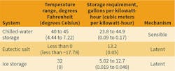
Table 1 provides typical design characteristics for each.2 In all cases, the medium, stored during off-peak periods and released during on-peak periods, is kept in a tank above or below the ground. Though each of the strategies is available to the design engineer, this article will focus on chilled-water storage, providing guidance for evaluating systems, including methods for determining economic feasibility.
Chilled-Water Storage
Chilled-water storage is a form of TES in which large quantities of chilled water produced from a central source are collected in a large insulated tank. Use of chilled-water storage in the United States increased during the 1980s, when many utility companies began offering financial incentives to customers as a means of balancing generating loads and delaying capital investments for additional capacity. Customers benefitted by reducing their peak electricity demand and costs, depending on the terms and conditions of their electricity-rate schedule.
Today, consulting engineers are recommending chilled-water storage for other purposes. For instance, if chilled-water storage cannot be justified based on energy savings alone, it sometimes is proposed as a source of chilled-water redundancy, fire- and life-safety water, leverage for favorable rate structures, construction or equipment rebates, and/or expanded chilled-water-plant capacity. Customers need to consider all of these factors before making such a large investment in capital and ownership costs. They also need to consider concerns with respect to design, such as weight, environmental impact, site conditions, and operation, as well as how a change in the utility rate or schedule could diminish utility-cost savings.
Electricity-Rate Schedule
Electricity-rate schedule is the most important factor to consider when analyzing the economics of chilled-water storage. Electricity rates include costs related to generation (operation of the electricity-generating plant), transmission and distribution (delivery of the electricity), fuel (coal, oil, natural gas, etc. used to fire the plant), and administration (management of the electricity-generation-and-delivery system). Other factors used to determine rates are plant capacity and electricity supply and demand during on- and off-peak times.
Utility companies manage rates by offering rate schedules according to customer type (e.g., residential, commercial, industrial). For each customer type, multiple rate schedules exist.
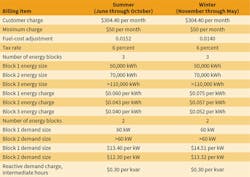
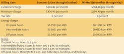
In the United States, the most common utility-rate structures are block (Table 2),2 seasonal (Table 3),3 and innovative (Table 4).2
Innovative rates are classified into seven categories2:
- Time of use (TOU).
- Real-time pricing (RTP).
- End use.
- Specialty.
- Financial incentives.
- Non-firm.
- Energy purchase.
This article will focus on TOU and RTP rates.
TOU are time-differentiated rates whereby the cost of electricity changes at specific times of the day, such as during on-peak and off-peak periods of energy and demand charges.
RTP are time-differentiated rates whereby the cost of electricity changes on an hourly basis.
Regardless of the rate schedule employed, an engineer must fully understand the rate to analyze the benefits of chilled-water storage accurately. This may involve the evaluation of other rate schedules offered by the utility company and a recommendation of an alternative rate schedule as a function of the customer’s needs, energy profile, and operation. The engineer needs to understand all of the rate features and ramifications, such as billing demand, power factor, ratchet clauses, fuel-cost adjustments, and service voltage levels. The text of rate schedules generally describes these factors in detail.
Tank Sizing
The sizing of a chilled-water storage tank is related to the cooling-load profile of a facility. The load profile dictates the control strategy—full storage or partial storage—to be used.
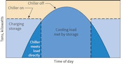
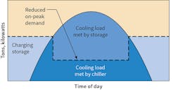
The full-storage strategy (Figure 1), called load shifting, produces total on-peak cooling load during off-peak times and discharges chilled water from a storage tank during on-peak hours while chillers are offline. Chilled-water storage tanks, then, are sized to carry the cooling load during on-peak hours. This normally is performed under a three-stage electricity-rate schedule: on-peak, immediate peak, and off-peak for the commodity and distribution portions of an electricity bill. The full-storage strategy has a higher capital cost, which includes a larger chiller and greater tank capacity and, thus, the need for more space.
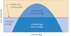
The partial-storage strategy (figures 2 and 3) is used to meet part of an on-peak cooling load. Partial storage is broken into two strategies: load leveling and demand limiting. With both strategies, the remaining load is provided by the chiller(s). The capital cost is lower because the chiller(s), piping and components, and storage tank are smaller and, thus, less space is needed. The operational controls, however, are more complex.
Load Profile and Tank Dimensions
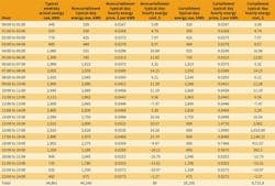
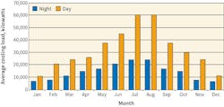
To estimate the design load for TES, an evaluation of facility electricity-load profile (Figure 4) is essential. This article assumes TES sizing based on an on-peak load of 5,000 tons and electricity generation, transmission, and distribution rates from the RTP and TOU schedules in Table 4. The RTP schedule takes into consideration the utility company’s charges and the owner’s load profile. The TOU rate schedule presents three distinct time frames: on-peak, immediate peak, and off-peak. Note that generation and transmission may be purchased based on energy (kilowatt-hours), instead of power (kilowatts) and energy charges.
Tank-Sizing Example
The tank used in this example will reduce eight hours of peak electricity. As a result, the tank will be sized to provide 40,000 ton-hours:
Tank loading = tons × hours
= 5,000 tons × 8 hours
= 40,000 ton-hours
The following properties and operating parameters are used:
Specific gravity (SG): 1.0
Specific heat capacity (Cp): 1.0 Btu per pound-mass, degrees Fahrenheit (4.19 kJ per kilogram, degrees Celsius)
Density (ρ): 62.4 lbm per cubic foot (1,000 kg per cubic meter)
Temperature difference (Tin − Tout, ∆T): 13°F (−10.56°C)
Storage efficiency (assumed) (ηst): 90 percent (to account for the fact the tank cannot be perfectly stratified and insulated)
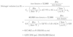
From these properties and operating parameters, storage volume (cubic feet) is calculated using the following equation5:
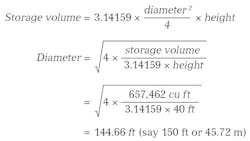
Hence, the tank is designed for nearly 5 million gal. (18,616,000 liters) of chilled-water storage. The tank dimensions can be of various heights and diameters, depending on manufacturer information, location, jurisdiction, etc. For this example, the tank is cylindrical with a height limit of 40 ft (12.2 m). The diameter is calculated using the following equation:
The dimensions of the tank, thus, are 40 ft high by 150 ft in diameter (12.2 m by 45.72 m). The tank is made of reinforced concrete. The choice of steel, concrete, or other material is important with respect to construction and ownership costs.
Pumping Energy and Cost
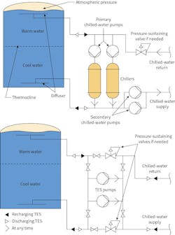
Stored chilled water is supplied to and returned from facilities by a system of pumps, piping, valves, and controls. Two conceptual pumping arrangements are shown in Figure 5. The top diagram shows TES connected directly to a plant; the bottom diagram shows TES connected remotely.
For proper evaluation of demand savings, pumping cost needs to be taken into account. In this example, TES is installed below ground and the head to deliver chilled water from the tank to the facility chilled-water system is 120 ft (36.58 m). Pump head is calculated based on the facility’s elevations and piping layout. The following information and calculations are used to calculate the anticipated electricity demand for chilled-water pumping from tank to system:
Pump head: 120 ft (36.58 m)
Motor/pump efficiency (ηpm): 75 percent (pump efficiency × motor efficiency = ηp × ηm = 78 percent × 97 percent)
Chiller-system performance = 0.60 kW per ton
Flow rate: 10,000 gpm (37,854 liters per minute)
Temperature difference (∆T): 13°F (−10.56°C)
Hours of operation: eight
Total power requirement = (gpm × pump head) ÷ (ηpm × 3,960)
= (10,000 gpm × 120 ft) ÷ (0.75 × 3,960)
= 404 hp
Pump and motor electricity demand = 0.746 kW per horsepower × 404 hp = 301.4 kW
Chiller-system electricity demand = 5,000 tons × 0.60 kW per ton = 3,000 kW
For complete calculations, obtain performance data for the entire chilled-water system (chiller, pumps, motor, cooling-tower fans, etc.). The key points are the operating components and energy are the same for chilled-water production and there is no electricity demand in the utility rate schedule during the off-peak period. The main purpose of the TES is to shift electricity-demand loads from on-peak times to off-peak times, which reduces electricity-demand (kilowatts) costs, not energy (kilowatt-hours).
Thus, the savings in on-peak demand per month is:
∆kW = 3,000 kW − 301.4 kW = 2,698.6 kW (say 2,700 kW)
Depending on the electricity rate schedule, the energy-consumption charge (dollars per kilowatt-hour) may be the same throughout the day. Nevertheless, the electricity-demand savings are calculated in Table 5. Chilled water is produced at night or during off-peak hours by the chillers. Based on component efficiencies, approximately 3,000 kW is required to produce and deliver 5,000 tons of chilled water. Without TES, the chillers in the plant operate during peak hours and at a higher cost according to normal utility rate schedules.
Emergency Backup
Another use of a TES system is backup source of chilled water in the event of an emergency. The use of TES for chilled-water backup is problematic if the tank does not charge properly and demand on the chiller plant is at peak with respect to rate schedule. And it can be expensive if managing loads becomes a problem. For example, if TES is designed for 40,000 ton-hours and the average peak demand is 50,000 tons over an eight-hour period, the TES would last for 48 minutes (5,000 tons × 8 hours × 60 minutes per hour ÷ 50,000 tons). The TES could last longer under a load-shedding program. For emergency purposes, the extreme case would be a loss of electrical power to the facility; hence, the entire chiller plant would be without power unless there were other means of providing electrical service to the plant (e.g., a diesel emergency generator system). Likewise, the facilities to which the chilled water is delivered would have to be backed up with an emergency power system.
A less extreme case would be the loss of a chiller during peak time. If a large campus needs to curtail the chilled-water load to a facility, one could ask if installing TES as a 48-minute backup system at a cost of $37 million is a good approach. The answer lies in a cost-benefit analysis of various means of providing emergency backup power. For example, compare the design, construction, and operation-and-maintenance costs of TES, a chiller, and a backup system with those of a new chiller system with backup power for a predetermined time. Almost always, the former will cost more than the latter.
Simple Payback and Life-Cycle-Cost Analysis
Methods commonly used by engineers to determine the financial pro forma of proposed energy-saving projects are simple payback (SPB) and life-cycle-cost analysis (LCCA). SPB is a straightforward method of evaluating an energy-saving project by determining the ratio of initial investment to annual energy-cost savings:
Simple payback (years) = investment cost ÷ dollar savings per year
This method forecasts the amount of time needed to recoup an initial investment through annual energy-cost savings. SPB considers neither the interest burden of funds nor operation-and-maintenance costs and, thus, is not considered an end-all for evaluating investments. For large projects, such as chilled-water storage, SPB should be used only as an initial measure of viability. Normally, a customer has a policy regarding the time within which it would like to recoup an investment through energy savings. For this example, the investment is $37 million, and the annual energy savings (from a previous engineering study) is approximately $200,000 per year. Thus, the SPB is:
Simple payback = $37,000,000 ÷ $200,000 per year = 185 years
Based purely on first cost vs. energy savings, implementation of this system cannot be justified.
For a more detailed evaluation, LCCA should be performed. LCCA considers a capital investment, ownership costs, the cost of money, and the life of a system. Ownership costs include costs such as operations (utilities, staff, etc.), maintenance (small equipment, parts, labor, etc.), repairs, and salvage value. The cost of money is the value a customer could realize if the funds were used for something else.
There are several methods of LCCA, including present worth, internal rate of return, and annual worth. The most commonly used is present worth. Net present worth (NPW) considers all of the aforementioned costs and savings and is the preferred method. The model is shown in Figure 6.
Initial investment cost includes studies, design, environmental abatement, removal of earth, permitting, the tank, controls, pump and piping systems, labor, construction equipment, the pump house, and landscaping. If a system will serve as backup to a main cooling facility, an emergency electrical backup system also needs to be considered.
Ownership cost is an important part of LCCA. Ownership cost consists of:
- Operational cost. Operational cost is made up of utility and manpower costs. Utility costs include fuel oil or natural gas for emergency diesel generators, electricity, and potable water. Manpower costs are real, but negligible, compared with other costs of operating a large TES system.
- Maintenance cost. Consisting of routine and non-routine servicing of a system, maintenance cost is more difficult to estimate accurately than energy cost. Non-routine maintenance includes water treatment and semiannual or annual inspection of tank internal surfaces, diffusers, piping systems, controls and instrumentation, flow meters, control-valve interfaces to distribution systems, pump and motor sets, controllers, landscaping, etc.
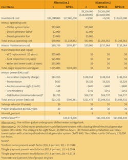
Table 5 shows an example of LCCA in which two alternatives to providing chilled water to a facility are compared. Alternative 1 is TES; Alternative 2 is a diesel generator (two different operating scenarios). Columns “1” and “2” represent today’s costs, while columns “NPW 1,” “NPW 2A,” and “NPW 2B” represent LCCA. The point of this analysis is to show the NPW values of both diesel-generator alternatives are less than the NPW value of TES. Table 5 presents no inspection and repair costs for the life of the system. The diesel-generator system does require inspection and repair, but based on experience with systems of this size, the cost is minor compared with that of a TES system. For a complete analysis, this cost should be included.
Expected-Value Method
Another way to evaluate installation of TES is to use the expected-value (EV) method (i.e., expected value of cost8). EV is used in finance and economics to evaluate possible alternatives and is defined as the average of all possible outcomes, weighted or adjusted according to the probability of occurrence. For use as backup to a chiller plant, a tank system is assumed to be completely reliable should the chiller plant fail. The key question concerns whether installing TES for purposes of backing up a chiller plant is worth the cost. In the simplest case, we are discussing a single mode of failure. To assist management with this very important question, this article provides a simple and realistic scenario consisting of predicted cost based on average campus salaries and an actual TES contract:
The campus uses chillers to provide cooling to various facilities. The chillers have no backup power or means of providing chilled water to the campus should the chillers fail. The facility consists of 20,000 employees (average salary of $150,000 per year, or approximately $72 per hour). The campus develops products worth $2 million per day. The campus could lose $2 million worth of products and labor totaling $11.5 million per day (eight-hour period). For continuous operation during an electrical outage, the customer is considering installing a TES tank system that will operate for 8 hours. The cost of construction, not including per-design and design cost, is $35 million (above-ground tank). The owner has adequate land space.
While the mechanical systems in the chiller plant may be reliable, factors such as the loss of utility service to the plant could arise. The reliability of the electrical service is important and should be taken into consideration by applying the theory of probability and the concept of EV. Based on history, the probability of an electrical failure is expressed in terms of a percentage. Therefore, the EV of savings is:
(savings − costs) × probability
= ($11,500,000 − $35,000,000) × 0.01
= −$235,000
The method yields a negative savings for an 8-hour period. If ownership cost is considered, the EV of savings is further on the negative side. The owner, then, should develop another strategy for providing chilled water or shut down operation for the day.
Conclusion
TES may or may not be a cost-saving proposition. There are many professionals in the energy industry who can assist in determining the best method of analysis for a project. Simple payback, life-cycle cost, and expected value are just three ways to evaluate alternatives; however, life-cycle-cost analysis takes other important factors into consideration.
References
- Moore, S. (2007, March). Ice harvesting in the 19th century. Retrieved from http://www.farmcollector.com/equipment/ice-harvesting-19th-century?pageid=1#PageContent1
- Krarti, M. (2010). Energy audit of building systems: An engineering approach (2nd ed.). New York: CRC Press.
- Pepco. (2014, August 1). Rate schedule time metered general service – Primary service, schedule MD-GT 3A.
- Wahidmohamed. (2012, January 14). Thermal energy storage using ice slurry. Retrieved from https://hvacing.wordpress.com/2012/01/14/thermal-energy-storage-using-ice-slurry
- ASHRAE. (2016). ASHRAE handbook—HVAC systems and equipment (pp. 51.7-51.9). Atlanta: ASHRAE.
- Thermal energy storage. (n.d.). Retrieved from http://what-when-how.com/energy-engineering/thermal-energy-storage/
- PJM. (2015). PJM manual 27: Open access transmission traffic accounting (sec. 5). Audubon, PA: PJM.
- Riggs, J.L. (1986). Essentials of engineering economics (2nd ed.). New York: McGraw-Hill.
As an adjunct assistant professor in the Mechanical Engineering department at The Catholic University of America, Adam K. Wolfe, PhD, PE, teaches graduate-level mechanical- and environmental-engineering courses, as well as undergraduate thermodynamics and fluid-mechanics courses. He has 32 years of experience as a professional mechanical and environmental engineer with the federal government, having served as a supervisory engineer with the U.S. Navy, the Architect of the Capitol, and the National Institutes of Health, leading and managing utility and engineering-management studies, as well as planning, design, construction, and operation-and-maintenance functions.
Did you find this article useful? Send comments and suggestions to Executive Editor Scott Arnold at [email protected].
