Methods of Calculating Water Recovery From Air-Conditioning Cooling Coils, Part 2 of 2
Last month, in Part 1 of this article, we evaluated four equations used to determine the amount of water vapor removed from cooling coils in condensate-recovery applications. The accuracy of those equations varies, as some calculate only the removal of water vapor entering with the outside-air intake. This month, we will discuss more-accurate methods of calculating water-vapor removal and calculating the removal of all water-vapor loads by a cooling coil.
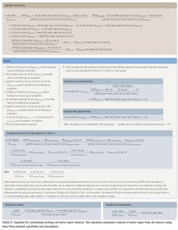
Equation 5
Unlike the previously discussed equations, Equation 5 (Table 6) calculates total cooling-coil water-vapor removal, or the removal of water vapor from all sources, such as people; air infiltration; the opening of outside doorways; water-vapor transmission through walls, floors, and ceilings; cooking; plants; cleaning; bathrooms; and pools. The problem is that it requires a considerable amount of information that engineers may not have or may not know how to obtain. Significant skill in psychrometrics, thermodynamics, and mass-flow analysis—not to mention considerable engineering time to produce an air-system diagram—is needed.
Equations 5a, 5b, and 5c are exact, while Equation 5d is approximate because of the use of EFLCH (equivalent full-load cooling hours per year). If Equation 5d is used, the gallons-per-hour value should come from a mass-flow analysis using air properties and ACFM (actual cubic feet per minute) airflows obtained through building design analysis and used in equations 5a, 5b, and/or 5c. Gallons per year can be obtained by calculating the gallons removed each hour of the year and totaling them, but this requires the selection of outside-air properties for each hour the air conditioner operates, a very time-consuming process of data collection and calculation. Equations 5aa and 5ab are similar to Equation 5a but approximate because they assume air specific volume is 13.3333 cu ft of wet air per pound of dry air.
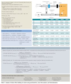
In Chapter 3 of the book “Alternative Water Sources and Wastewater Management,”4 an example calculation of cooling-coil water-vapor removal is given for an office building in Dallas. I decided to use this example in my article and, thus, extrapolated additional detail on this system in a mass-flow-analysis diagram in Table 7. Some of the psychrometric air properties and airflows were provided, while the rest were calculated using provided information. The diagram shows the psychrometrics, including ACFM airflow, mass dry-air flow, mass water-vapor flow, and energy flow, at six points in the system. Heat from fans was not included to keep the analysis simple. In this case, the only source of water vapor is outside-air intake, at a rate of 20.2737 lb per hour. The building exhaust removes 14.4507 lb of water per hour, leaving 5.8230 lb to be removed by the cooling coils.
The easiest way to calculate cooling-coil water-vapor removal involves the use of Method A (Equation 5a), which utilizes the properties of air at the inlet to and leaving a cooling coil. In the case of the Dallas office building, the outside-air-intake and recirculation-duct airflows were added together (using mass-flow analysis) and analyzed to determine the air-property mixture, or coil-inlet airflow (Point 5 on the diagram). Then, using Method A (Equation 5a), the amount of water-vapor removal by the cooing coil (5.8230 lb per hour) was determined.
Like Method A, Method B is accurate, but breaks air entering a cooling coil into two streams—recirculation-duct return (Point 3 in the diagram in Table 7) and outside-air intake (Point 4)—and analyzes them separately as they pass through the cooling coil. The results for Method B in Table 7 show the water-vapor removal related to outside-air-intake flow over the cooling coil is 5.8230 lb per hour and the water-vapor removal associated with recirculation-duct airflow across the cooling coil is 0 lb per hour for a total water-vapor removal of 5.8230 lb per hour, which is the same as Method A. It should be noted that, in this case, there is no internal building water-vapor generation (from people, etc.); therefore, there is no water-vapor removal from recirculation-duct airflow. In other words, the humidity ratio of the recirculation-duct airflow is equal to the humidity ratio of the air leaving the coil; therefore, there is no excess water vapor to be removed.
Method B uses Equation 5b, which calculates water-vapor removal for the two air steams (outside-air intake and recirculation duct) separately. You can see that Method B calculated the same water-vapor removal as Method A, which uses only the air entering the cooling coil. This proves Method B is accurate. Method A and Method B worked very well in this case, in which the only water-vapor source was the outside-air intake; it works just as well for buildings with multiple sources of water vapor because it uses the principles of mass-flow analysis.
As mentioned earlier, the airflow diagram in Table 7 is an extrapolation of provided data. Cooling-coil heat removal was given as 5 tons (60,000 Btu/hr). Because the amount of water-vapor removal is rather small, the bulk of the heat removal is sensible-heat removal. The temperature and relative humidity of the air leaving the cooling coil were stated to be 58°F and 90 percent, respectively, which allowed us to calculate the properties of the air entering the cooling coil. This allowed the calculation of the recirculation-duct air properties. The exhaust airflow was chosen to be 1,566.4701 lb of dry air per hour, the same as the outside-air intake and, thus, balancing the air in the building. With the exhaust airflow identified, iterations were completed to identify the return-air properties. The return-air dry bulb of 82.97°F is slightly elevated over a common air-conditioning-season comfort set point of 75°F and 50 percent RH (W = 0.009236 lb per pound). The humidity ratio of the return air is very comfortable. The reason for the high dry bulb is the small amount of water-vapor removal, which means the bulk of the 60,000-Btu/hr heat removal is sensible heat. A typical office building usually has more latent-heat removal than this analysis shows, but that is because this example assumes the only water-vapor source is the outside-air intake.
Next, we will consider the impact of water vapor from people. The Dallas office building has an outside-air intake of 375 ACFM, which suggests occupancy of 18 or 19 people (375 ACFM ÷ 20 ACFM per person = 18.75 people). The average air-conditioning load for a typical office building is about 42.86 Btu/hr per square foot, or 280 sq ft per ton. With a design load of 5 tons, or 60,000 Btu/hr, the building square footage is around 1,400 (280 sq ft per ton × 5 tons = 1,400 sq ft). With an assumed occupancy of 18, then, the water-vapor load from people is around 4.1814 lb per hour. If we input this added water-vapor load into the building mass-flow analysis, we get the results in Table 8.
In summary, the addition of water vapor from people increased cooling-coil water-vapor removal 57.44 percent, from 5.8230 lb per hour to 9.1679 lb per hour. Excluding pool rooms, outside-air intake and people usually are the two greatest sources of water vapor in commercial buildings. This review shows the importance of looking beyond outside-air-intake water vapor when estimating the amount of water vapor removed annually by a cooling coil. It also shows the importance of mass-flow analysis and psychrometrics, which allow engineers to develop a diagram like the one in Table 7 to fully understand system operation and the load on a cooling coil.
There are computer programs to help engineers perform these calculations. One such program is TRACE from Trane. This program develops airflow diagrams and calculates mass flows. Also, it has hourly psychrometric air properties for different cities in the United States.
Work by Lawrence
Just before the completion of this article, the author came across some in-depth work5,6,7 led by Thomas Lawrence, PhD, PE, LEED AP, program coordinator for mechanical engineering at the University of Georgia. What is unique about this work is the amount of effort put into getting accurate values of gallons per year and then developing that data into (gal. per year) ÷ ACFMoutside-air intake.
Table 3 in a May 2012 article co-written by Lawrence5 summarizes this data for 46 cities in two columns: “Weather Data Predicted” and “Regression Equation Predicted Values.” The values in the first column came from a very time-consuming spreadsheet analysis calculating water removal for each hour of the year. Gallons collected per year then were divided by outside-air-intake ACFM. The equation used in the spreadsheet analysis is:
This equation assumes the air leaving a cooling coil will be at a humidity ratio of 0.008 lb water vapor per pound of dry air. The equation also assumes only 90 percent of the water is captured. The ACFM (cu ft wet air per min) is the outside-air-intake airflow bringing in the water-vapor load.
To determine gallons of water-vapor removal per year, the above equation uses outside-air humidity ratio (Woutside-air intake) for each of the 8,760 hr in a year, using historical hourly psychrometric data. The ACFM in the above equation is ACFMoutside-air intake, which is assumed to remain constant over the course of a year. Outside-air-intake air density is an assumed 0.0765 lb of dry air per cubic foot of wet air. If you instead use actual outside-air-intake air density for each hour of the year with an assumed ACFM, you will get a slightly lower gallons-per-hour or gallons-per-year value.
Another method of calculating gallons per year is offered in the May 2012 article, which has factors for use with ACFMoutside-air intake in the following:
If a system is not allowed to run for certain hours or days, when the outside-air humidity ratio is above 0.008 lb of water vapor per pound of dry air, consider developing your own spreadsheet to calculate gallons per year.
Once data for each city were established, Lawrence developed an equation that uses weather data to produce a value of gallons per year per ACFM. Results of that equation can be found in the “Regression Equation Predicted” column of Table 3 in the May 2012 article. The “Regression Equation Predicted” data fared well in comparison with the highly accurate “Weather Data Predicted” (detailed spreadsheet method) data. The regression equation is:
where:
dew-point temperature = average annual dew-point temperature, degrees Fahrenheit
CDD = cooling degree-days, 65°F basis
in. rainfall = accumulation from April through October, inches
It is important to note that this series of calculations is for outside-air-intake water vapor condensed and collected only; it does not include any other sources of water vapor.
A Fall 2010 article co-written by Lawrence6 has a map of the United States showing values of condensate-collection potential for different regions of the country. The values are in (gal./year)/ACFMoutside-air intake.
Lawrence conducted a spreadsheet analysis for a research laboratory in Athens, Ga., with 100-percent-outside-air intake of 19,400 ACFM. The air-handling system ran all year long. According to the hourly outside-air humidity ratios, the air conditioner dehumidified for 4,593 hr over the course of a year, which is the number of hours the outside-air humidity ratio exceeded 0.008 lb of water vapor per pound of dry air. The value of 4,593 hr of cooling per year is interesting compared to the EFLCH for Atlanta in Table 4 (Part 1 of this article).
Conclusion
This article analyzed equations engineers use to calculate the amount of water vapor removed from cooling coils. Some of the equations are accurate, while others are approximate. Many are for only one source of water vapor: outside-air intake. This article explained procedures that consider water vapor from other sources. It is hoped this article provided insight into the many procedures used to calculate water-vapor removal from cooling coils.
References
4) Boulware, E.W. B. (2012). Alternative water sources and wastewater management (ch. 3). New York: McGraw-Hill Professional.
5) Lawrence, T., Perry, J., & Alsen, T. (2012, May). AHU condensate collection economics. ASHRAE Journal, pp. 18-25.
6) Lawrence, T., & Perry, J. (2010, Fall). Capturing condensate. High Performing Buildings, pp. 56-61. Available at http://www.hpbmagazine.org/attachments/article/12072/10F-CapturingCondensate.pdf
7) Lawrence, T., Perry, J., & Dempsey, P. (2010, January). Capturing condensate by retrofitting AHUs. ASHRAE Journal, pp. 48-54.
The president of Acker & Associates, a consulting engineering firm he founded in 1996, and a longtime member of HPAC Engineering’s Editorial Advisory Board, William G. Acker is considered an expert in psychrometrics, mass-flow analysis, and water-vapor transmission. Along with colleague Nels E. Strand Jr., he has developed more than 50 computer programs used to solve problems, determine energy flows, and calculate air-pollution emissions. The programs are highly recognized by engineers with The National Institute for Occupational Safety and Health, ASHRAE, the North American Insulation Manufacturers Association, the National Roofing Contractors Association, the Association of Energy Engineers, and the U.S. Environmental Protection Agency. He can be reached at 920-465-3548.
Did you find this article useful? Send comments and suggestions to Executive Editor Scott Arnold at [email protected].


