Maximizing Outdoor-Air-Economizer Operation
Many HVAC systems are equipped with 100-percent-outdoor-air economizer cycles consisting of a set of dampers that steer cool outdoor air to fans, which then move the air around the system. The purpose of an air economizer is to reduce refrigerant-compressor run time during colder months and possibly during cool night hours and, thus, lower annual energy consumption.
Many variable-air-volume (VAV) systems are designed with incompatible and/or incomplete control strategies that undermine the performance of outdoor-air economizers. This problem has persisted since the late 1970s, when some 90 percent of VAV systems did not function as expected, and some 60 percent did not achieve predicted energy savings.¹ This article discusses how, through proper application of modern tools, such as direct digital control (DDC) and highly accurate, low-cost instruments, a much higher level of success can be achieved. It is important to note that many of the methods discussed in this article are not industry-standard practice, but nonetheless worth considering in the name of controllability, performance, and energy efficiency.
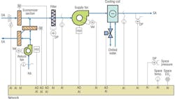
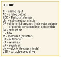
Economizer OptionsEconomizer systems essentially come in one of two configurations. The first uses a traditional supply-fan-and-return-fan design, with an outdoor-air intake damper, a return-air damper, and an exhaust-air damper (Figure 1). This type of system, sometimes called “push-pull,” depends on the return fan to handle return-air-system losses and the supply fan to handle supply-air-system losses. Economizers should be integrated (sequenced) with cooling-coil operation for best system efficiency and performance in constant-air-volume applications.
The second configuration uses the same three dampers to steer air, but has a relief/exhaust fan instead of a return fan to control space pressure (Figure 2). The relief/exhaust fan is located just before the exhaust-air damper and is not directly in the path of return air. The supply fan overcomes supply- and return-air-path pressure losses, while the exhaust fan is sized to handle just return-air-path losses.
In years past, a common control strategy for relief/exhaust systems was to start the relief fan when the exhaust damper opened beyond a certain point. The relief/exhaust fan would be on or off, sometimes causing space-pressure fluctuations and control dithering; as a result, economizers tended not to be integrated and were switched on at 100 percent or switched off, depending on outdoor ambient temperature. An integrated-economizer strategy with on/off (non-modulating) exhaust fan caused space-pressure fluctuations that were difficult to stabilize; consequently, such a strategy generally was not used, except in medium and small packaged air-conditioning systems with non-integrated economizers, in which direct-expansion compressors were switched off while the economizer was switched on.
With the analog (pneumatic/electronic) controls available during the 1970s, the dampers in constant-volume push-pull systems were controlled as one, with the return-air damper articulated at 180 degrees to the outdoor- and exhaust-air dampers so that a single linear control signal would open the outdoor- and exhaust-air dampers while closing the return-air damper. Minimum outdoor-air-intake flow was achieved by limiting the signal to the dampers so they would not fully seat in the full return-air position. The 10-to-15-percent signal limit caused the outdoor-air damper to open slightly to provide ventilation air. Occasionally, a separate minimum-outdoor-air intake with separate two-position damper allowed the economizer-damper section to go to the full return position at zero signal output. This method of providing ventilation air, while a bit inaccurate, was satisfactory in the days when the amount of outdoor air admitted was not as critical as it is now.
Technically speaking, with a constant-volume push-pull system, the outdoor- and exhaust-air dampers are not needed for control to have a fully functioning economizer. The return-air damper alone can steer the return air either outdoors or back to the supply fan, depending on its position. This assumes the supply and return fans operate at a constant flow differential to offset general exhausts and establish a positive space pressure, providing for perimeter exfiltration (crack) losses. While this method has been successful, it seldom is used as a design standard because inlet and outlet conditions have to be ideal.¹
When VAV-system designs were adopted, inlet vanes were added to the supply and return fans to control their capacity. This made responding to variable-air zone terminals possible; however, economizer-cycle design and control were not changed. What’s more, the return-fan-inlet-vane control signal mistakenly was slaved to the supply-fan control signal. The non-linear relationship between the supply and return fans generated outdoor-air-intake rates that varied from negative to positive because of plenum-pressure changes associated with inaccurate return-fan tracking. Ventilation flow usually was tested at 100 percent, which seldom occurs in VAV systems, but is where fans, including minimum outdoor-air intakes, easily can be adjusted, tracked, and verified.
Differences in plenum pressure from improper return- and relief-fan control have been known to cause air to flow backward through exhaust-damper openings. This problem tends not to exist with constant-volume systems because plenum pressure is maintained so exhaust air exits through the exhaust opening, outdoor-air-intake air comes in through the outdoor-air damper, and the return-air damper steers proportionally, depending on the magnitude of the damper control signal.
Economizer Design for VAV Systems
Demands on VAV air-delivery systems have intensified considerably because of indoor-air-quality (IAQ) dictates and energy-code mandates. The two economizer-system types require the application of the correct operating strategy, if they are to accomplish their mission.
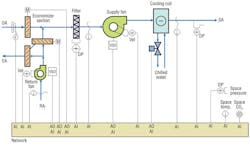
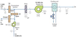
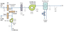
When using a return fan, one method of control is to track the return fan to the supply fan volumetrically so differential airflow is maintained (figures 3 and 4). By definition, a volumetric tracking strategy ensures the minimum-outdoor-air-intake rate established by the designer is maintained through the range of system operation as determined by the formula:
OA = SA − RA
where:
OA = outdoor airflow
SA = supply airflow
RA = return airflow
Though not an industry-standard practice, volumetrically tracking return fans with the outdoor-air damper operated in a two-position mode (supply fan on, damper open; supply fan off, damper closed) results in maximum system efficiency, except during warm-up and cool-down cycles when the tracking offset is set at zero. Remembering that airflow differential is fixed by fan-tracking ratio, a wide-open outdoor-air damper exacts very little pressure drop at minimum outdoor airflow, minimizing the impact on supply-fan energy. The return-air and exhaust-air dampers then are free to modulate proportionally, providing linear air steering; the minimum outdoor-air-intake flow for ventilation can be maintained easily without the partially closed outdoor-air damper causing pressure losses, which tend to upset the natural plenum-pressure balance (sometimes causing outdoor air to enter backward through the exhaust opening2). When using volumetric fan-tracking techniques, proper control through P, I, and 1/D terms using accurate air-velocity transmitters promotes stable system control with accurate differential airflows.¹ In cases in which the minimum design outdoor-air intake is more than the general and toilet exhaust fans can remove, excess space-pressure rise will occur. A space-pressure proportional-integral-derivative (PID) controller can sense this increase in pressure and modulate the return-air/exhaust-air dampers toward the exhaust-air position to equalize the space pressure on a consistent basis (usually ~0.004 in. wc).
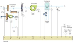
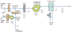
While control of the exhaust/relief-fan configuration (figures 5 and 6) should be simple, maintaining code-required minimum airflow as supply volume varies can be difficult. A strategy that works reliably is space-pressure control. To accomplish this, one must find the best place to sense space pressure. A stable ambient reference has to be provided for the pressure transmitter; otherwise, the transmitter will be affected by wind-velocity pressure. (This is a key element that has to be validated in much the same way as return-fan differential-flow-tracking signals have to be validated for an air-delivery system to work accurately and effectively.) A pressure reset schedule then can be applied to set the required minimum outdoor-air intake. This involves adjusting the space-pressure setpoint up or down within limited bounds while the economizer cycle is not in operation. These bounds are 0 in. wc to 0.01 in. wc, with a control setpoint somewhere around 0.004 in. wc, just below the relief/exhaust-fan pressure setpoint. Note that when more than one air-handling unit serves a space, the relief/exhaust fans must respond to the same space-pressure speed command signal so no differential flows that would cause wind tunnels in corridors are established. This sometimes happens when multiple packaged units supply common floors and/or a looped ductwork system.
Mixing economizer-system types and control strategies can cause all sorts of interesting issues. For example, using a traditional return fan and controlling it by space pressure becomes problematic when the economizer is off because the return fan operates against a constant orifice and tends to lag the supply fan because of a loss of control. When the supply fan speeds up to satisfy the duct-static-pressure-control requirement, the outdoor-air-intake volume increases. When it does, space pressure increases, caused by overventilation at the hottest time of the year, during the peak utility-demand window. At other times, the return fan provides resistance to the airflow by not keeping up with the supply fan, causing increased negative pressure in the plenums and increased outdoor-air-intake flow, some of which can enter through the exhaust opening, possibly causing contaminated air to enter the system as if it were fresh air. (Outdoor-air intake through exhaust openings can bring in exhaust fumes from trucks parked at loading docks, where exhaust-air openings often are located.)
For large systems in multiple-story buildings, a traditional return fan is needed to move air back through a higher-resistance duct path than would be found in a single-floor common-plenum-return design. Smaller systems often are served more cost-effectively by relief/exhaust fans or stand-alone variable-speed general exhaust fans responding to space pressure alone. This is because return losses usually are smaller and the spaces more uniform in nature (e.g., single story with a common ceiling plenum). Many successful economizer applications use factory-packaged outdoor-air and return-air economizer dampers with integrated or separate relief/exhaust fans with electronically commutated motors and variable-speed control responsive to space-pressure rise.
Action Tools for Economizer Design and Control
When configuring larger HVAC systems with return fans and economizers, consider:
• Providing variable-frequency drives (VFDs) to control supply- and return-fan capacity.
• Providing factory piezometer-ring or velocity-pressure airflow elements in fan inlets with accurate transmitters designed for volumetric airflow tracking. The fan manufacturer can provide certified pressure/flow curves with differential-pressure ranges for proper selection and calibration of each velocity or flow transmitter.
• Providing parallel-bladed outdoor-air-intake dampers that open when the supply fan is enabled. Parallel-bladed dampers provide linear air mixing when upstream pressures are low and constant.
• Providing accurate third-party-tested airflow-monitoring sensors for control, validation, and trending of outdoor-air intake, typically at low air velocities.
• Providing modulating parallel-bladed return-air and exhaust-air dampers for air-steering control using the outdoor-airflow-measurement signal and PID loop to maintain the required minimum outdoor-air intake at setpoint.
• Providing a separate control output for the outdoor-air damper so it can be left open while the exhaust-air and return-air dampers modulate to maintain temperature control and/or demand control ventilation.
• Controlling the return fan based on flow-tracking offset to provide enough outdoor-air makeup to offset general exhaust fans and provide slightly positive space pressurization (code-mandated minimum space ventilation).
• Controlling the return-air/exhaust-air dampers in sequence with the cooling-coil control valve when outdoor air is below the high dry-bulb-temperature limit (enthalpy control optional).
• Resetting the economizer (return-air/exhaust-air dampers) to increase the outdoor-air intake to between the limits of 0.15 cfm per square foot to 15 cfm per person (ANSI/ASHRAE Standard 62.1, Ventilation for Acceptable Indoor Air Quality) when using zone carbon-dioxide (CO2) sensing for IAQ.
When configuring medium to small HVAC systems with packaged or built-up configurations, consider:
• Providing VFDs to control supply and relief exhaust-fan capacity and provide energy control and demand information.
• Providing accurate, third-party-tested airflow-monitoring sensors for control, validation, and trending of outdoor-air intake, typically at low air velocities.
• Providing modulating parallel-bladed outdoor-air and return-air dampers for air-steering control.
• Providing a parallel-bladed exhaust-air damper that opens when the relief exhaust fan is enabled.
• Controlling the relief exhaust fan(s) based on space-pressure rise over setpoint of 0.004 in. wc when in economizer or CO2-demand-control-ventilation-reset mode.
• Switching the space-pressure-control output to the outdoor-air damper (leaving the return-air and exhaust-air dampers in the full return-air position) to maintain space pressure between 0.001 in. and 0.004 in. wc when not in economizer mode. Outdoor-air intake is verified by the flow sensor in the outdoor-air opening and actual flow trims.
• Ensuring the relief/exhaust fans serving spaces served by two or more air-conditioning units follow the same space-pressure-control PID-loop output signal to prevent differential air currents from flowing through corridors and spaces.
• Enabling the economizer cycle and allowing the outdoor-air/return-air dampers to increase outdoor-air intake to between the design limits of 0.15 cfm per square foot and 15 cfm per person—verified by a certified testing, adjusting, and balancing contractor—when using zone CO2 sensing. Let the relief/exhaust fan modulate to control the space-pressure rise resulting from increased outdoor-air intake at the correct space-pressure setpoint.
Conclusion
The scenarios discussed in this article are relatively simple and modular in nature. Using the correct tools for a given system design is essential to effective economizer operation, which, at the outset, seems simpler than it is when all of the demands placed on these systems in today’s environment are considered. Different system types dictate different control treatment for successful economizer operation to be accomplished and legal and traceable minimum ventilation rates to be ensured. System demands for IAQ control and mandated energy optimization can be applied easily, once an understanding of system operating variables, dynamics, and demands is gained. It is hoped the reader has found some useful tips and techniques for effective economizer application and successful air-side operation here.
References
1) Air Monitor Corp. (1987). Designers manual for airflow control of VAV systems.
2) Seem, J.E., House, J.M., & Klaassen, C.J. (1998, February). Volume matching control: Leave the outdoor air damper wide open. ASHRAE Journal, pp. 58-60.
A principal for H & P Systems Inc., Craig F. Hofferber, CxA, CSI, specializes in mechanical-, electrical-, instrumentation-, and control-system design; construction coordination; and system commissioning. His hands-on systems knowledge is coupled with extensive manufacturer and product knowledge.
Did you find this article useful? Send comments and suggestions to Executive Editor Scott Arnold at [email protected].
