The condensate trap perhaps is the most overlooked item in the design and installation of fan coils and air handlers with cooling coils. Often, condensate traps are inadequately described in contract documents and, sometimes, are not described at all, which leaves important details to be determined by the installing contractor. It is the designer, however, who is in the best position to make these decisions because of his or her knowledge of the pressures in the air-distribution system.
There are widespread misconceptions about how condensate traps work and how to properly size them, and often, little or no thought is devoted to simple, inexpensive details that can make them much easier to inspect and maintain.
Review
The purpose of one of these traps is to allow accumulating condensate to drain off while preventing air from entering a draw-thru unit or escaping a blow-thru unit. A cooling coil’s drain-pan opening is located at the point in an airflow system where the air pressure—either positive or negative—is the greatest. It makes sense to prevent an air “leak” at this location, especially in view of the effort we typically expend to seal and pressure-test system ductwork. However, even if we were not concerned about leaking air, draw-thru units would allow little or no condensate drainage if not equipped with a properly designed trap.
In short, the fundamental purpose of one of these traps is to use a column of condensate in such a way as to prevent air movement into or out of the equipment casing, while still allowing the condensate to drain away.
Potential Problems
An improperly constructed or missing trap can cause the following problems.
No trap or trap outlet too low. For draw-thru units in either of these situations, condensate accumulating in the pan will be subjected to a “jet” of incoming air, which often results in spray being carried over into the fan-inlet area. This sometimes is referred to as “geysering.” For blow-thru units, escaping air may be the most serious consequence, but in the presence of copious condensation, a turbulent air/water mix in the pan also may cause some spillage or spraying of water downstream of the coil.
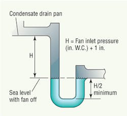
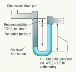
Trap outlet too high. In draw-thru units with this problem, an air seal will be maintained; however, if the condensate’s net “column” height in the trap (“H” in the accompanying figures) is less than the equipment’s negative air pressure in inches of water column, the condensate will be unable to drain away. This will cause the accumulating condensate to overflow the pan into the surrounding parts of the equipment casing (sometimes referred to as “floodback”). In a blow-thru unit, an outlet as high as the inlet will work during fan operation as long as the rest of the trap is properly dimensioned. However, one school of thought holds that it is best to specify the outlet a little lower (at least 1/2 in.) than the inlet. Providing this little extra “head” at the trap inlet will assist in draining the pan of residual condensate after the fan is stopped. To discourage microbial growth, it is best to keep the pan as dry as possible during fan-off periods.
One trap shared by two or more fan-coil units. If one of the fan-coil units sharing a trap is shut down, the other(s) will blow air into or draw air from the inactive system, depending on whether the units are of the draw-thru or blow-thru variety. For this reason, each fan-coil unit should have its own trap.
Dry trap. A common problem in very arid climates and during periods when cooling coils are inactive, such as winter, is evaporation of the water in traps. A liquid seal can be maintained by either continuous drip or intermittent trap “priming.” Designers uncertain whether or not evaporation occurs or who anticipate that it does should specify either a means of priming or trap features that will allow priming to be easily added later. A dry trap on a draw-thru unit can be the source of objectionable odors and noxious fumes in a building. (At a military air base in the desert, a draw-thru air handler was located near a flight line. While the unit’s fresh-air intake was located well away from any source of contaminated air, the floor drain for the trap was not, and building occupants were sickened by the fumes of burned jet fuel inducted through the dry trap. Priming the trap solved the problem.) Priming water should be applied to the downstream side of the trap, and care should be taken to assure adherence to plumbing codes regarding air gaps for protecting potable-water sources.
Draw-thru Traps
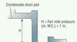
Figure 1 shows the necessary dimensions of a trap on a draw-thru unit and the maximum level of condensate that can exist in such a trap with the fan off. The recommended safety factor of 1 in. added to the casing pressure is a reasonable balance between the need to account for unanticipated increases in that (negative) pressure and the practical need to keep the total trap depth (L) to a minimum, especially on pad-mounted equipment. Many traps are improperly installed because dimension “L” was not taken into account in mounting the air handler high enough to accommodate the trap.
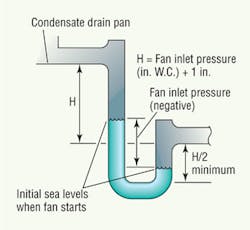
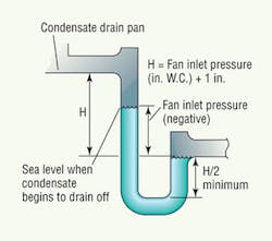
Figure 2 shows the position of the condensate columns when the fan starts, while Figure 3 shows the water levels when enough condensate has accumulated in the trap to begin draining away.
Blow-thru Traps
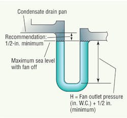
shows the required dimensions of traps on blow-thru units and the maximum level of condensate that can exist in such traps with the fan off. Here again, the 1-in. safety factor is a practical recommendation for accounting for an increase in casing pressure caused by a situation beyond the designer’s control (e.g., filter loading, higher installed duct losses, etc.). In most systems, 1 in. of water gauge is a significant percentage of the casing air pressure. Of course, the designer can increase the calculated equipment pressure as necessary.
Figure 5 shows the condensate-column levels when the fan starts. After the fan starts, additional condensate coming from the pan drains away. Again, it is important to take into account the total trap depth—dimension “L”—to ensure an adequate mounting height for the air handler.
Recommendation
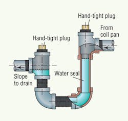
A trap with two tees and plugs, as shown in Figure 6, allows easy access for inspection, cleaning, and, if necessary, priming. Although the plugs can be wrench-tight, a hand-tight condition usually prevents air leakage on the inlet side, and one does not have to have a wrench to inspect the trap. The purpose of the plug on the outlet side is to keep dirt, small animals, and insects out of the trap. Traps commonly are constructed of either copper or plastic pipe. Although Figure 6 shows a draw-thru trap, tees and plugs can, of course, also be used for traps on blow-thru units.
Under the pressure of design deadlines, it often is difficult to pay the attention to detail that all projects deserve. In the matter of condensate traps, however, a couple of simple, standard drawings in a designer’s CADD repertoire, with fill-in-the-blank dimensions, will go a long way toward demonstrating completeness of design and preventing problems.
Ronald F. Brusha obtained a degree in mechanical engineering from California State University at Los Angeles in 1962. Most of his professional experience has been as a civilian employee of the U.S. Army Corps of Engineers. In 1992, he retired as chief of the Construction Technical Support Section of the Los Angeles District Office of the Corps.

