Part 1 of this article (August 2011) reviews the basics of air-side-economizer operation and illustrates psychrometric analysis of a small office zone. This part, Part 2, illustrates psychrometric analysis of a church sanctuary, demonstrating that excessive space humidity can occur with high limits allowing economizer operation when outdoor dew-point temperature significantly exceeds occupied-space dew-point temperature.
Church-Sanctuary Example
Economizer design for buildings with low occupant density, such as offices, is straightforward and without significant risk of problems because the room-load sensible-heat ratio is relatively high, with a small triangle of outdoor state points lying above the room-load process line. This is not true of zones with high occupant density, such as church sanctuaries.
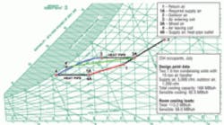
Figure 6 shows the cooling-system design point for a church sanctuary in Minneapolis served by a 15-ton DX (direct expansion) air handler on two 7.5-ton condensing units. As before, the occupied-zone design point is 76°F at 50-percent RH. Outdoor ambient is the American Society of Heating, Refrigerating and Air-Conditioning Engineers-stated 0.4 percent cooling design point for Minneapolis: 91°F DB at 73.5°F MCWB. Note that the sanctuary (room) process line—1 to 1A—is steep and does not intersect the saturation line. The steepness is caused by the latent load of 234 occupants. Also, the temperature at Point 1A, which is the maximum temperature needed to achieve the room design point, is 63°F. No DX air-conditioning system can follow this process line; even if one could, the coil leaving temperature of 63°F would be too high for effective dehumidification.
The green line from Point 3A to Point 4' in Figure 6 is the process line for the 15-ton cooling coil at coil-inlet conditions of mixed-air Point 3A. Supply air delivered to the sanctuary at the conditions of Point 4' clearly cannot satisfy moisture-removal requirements. Moisture conditions only will be made worse by the large sensible capacity of the unit, which will result in short run times and long off times.
The solution here is a heat pipe, which allows both a low coil leaving temperature (Point 4) and a nearly ideal supply-air temperature and dew point (Point 4A). (A system with hot-gas reheat also was considered, but would have required a larger [20 tons] unit and resulted in longer run times for dehumidification and higher energy costs.)
A heat pipe is a passive coil wrapping around an air-conditioning-unit cooling coil. It has a sealed charge of refrigerant that transfers heat from the air entering a coil to the air leaving the coil. Heat pipes are specified in terms of the temperature difference between entering and leaving air. For the heat pipe in Figure 6, the temperature difference is 12°F.
Figure 7 shows an economizer operating at two points. Point 2—61°F with 90-percent RH—is the same as in the office integrated-operation example. Point 3, the mix of outdoor and return air, is at the exact temperature needed to maintain the room set point of 76°F, as the control—outdoor-air-, relief-, and return-damper modulation—is perfect. The operating relative humidity, shown by Point 1', is higher than design, but still an acceptable 62 percent.ii Point 2" is at the maximum temperature at which the economizer can operate without mechanical cooling—the same temperature as Point 1A, but at 90-percent RH. The dew-point temperature at Point 2" is nearly 12°F higher than that at Point 1A, which is needed to maintain the design point of 50-percent RH. Sanctuary relative humidity will exceed 70 percent, as shown by the gray process line going from Point 2" to Point 1".
The gray lines illustrate the removal of heat and moisture from the room by the 5,000 cfm supplied by the economizer will follow the slope of the calculated load process, 1A to 1. This illustrates the pitfall of using the dry-bulb economizer limit alone when room sensible-heat ratio is steep. In this example, the dew-point limit of 58°F (passing through Point 2) would avoid exceeding 65-percent RH in the sanctuary, as would using the electronic enthalpy "A" curve (red triangles).
Figure 8 shows integrated operation, with the economizer delivering 100-percent outdoor air and the air-conditioning system operating to control space temperature. Outdoor conditions are 67°F at the suggested dew-point limit of 58°F. The air-conditioning system is assumed to be operating at half load on one of the two condensing units, and the heat-pipe temperature change is assumed to be half of design, or 6°F. Point 4A is the delivered supply air, based on the assumed heat-pipe temperature change and manufacturer performance software run at the coil-inlet condition, Point 2A. The process line from Point 2A to Point 4 is coil performance at half load.iii
Depending on the outdoor temperature, the air-conditioning unit will cycle at part or full load to maintain the design room set point. Figure 9 shows the room conditions with the system running (Line 4A to 1') and cycled off (Line 2 to 1"). It seems likely the achieved room relative humidity will be about 60 percent, as shown by the "+" on the line connecting points 1' and 1".
Selecting a dew-point limit above 58°F or using a fixed enthalpy limit may risk operation with marginal or unacceptably high humidity.
Conclusions
These examples demonstrate the importance of engineers examining room or zone loads at conditions at which economizer operation is limited, with the expected internal loads (people, lights, etc.). The room-load process line then can be plotted on a psychrometric chart. Supply-air conditions under economizer operation fit into one of three cases:
- Blended outdoor and return air, as shown in figures 4 and 7.
- 100-percent outdoor air when room load equals the capacity of the economizer alone, as shown in figures 4 and 7.
- 100-percent outdoor air with air-conditioning-unit operation (chilled water or DX) to achieve room-temperature set point, as shown in figures 5, 8, and 9.
Final room conditions can be estimated by assuming supply air will follow the slope of the room-load process line as it picks up heat and moisture.
The examples discussed here illustrate that using dry-bulb-temperature limit alone in humid climates can result in loss of room humidity control.
With integrated control, single-capacity DX systems are appropriate only with dew-point or electronic enthalpy control and loads having a high sensible-heat ratio. In all cases, the most increments of capacity control available should be specified. Even with capacity control, integrated operation of DX units will not deliver constant room-air temperature.
With integrated operation of chilled-water systems, chilled-water flow can be regulated to provide constant room-air temperature. However, when conditions are warm and humid, as depicted in figures 5 and 8, the same problems of moisture control occur because, at reduced chilled-water flow, the supply air may not be cooled sufficiently for dehumidification. A study published in 20082 offers further insights into economizer control of chilled-water systems.
Psychrometric analysis allows designers to evaluate economizer operation with different high-limit controls and to select controls and capacity modulation to avoid occupant discomfort during economizer operation.
Notes
ii) Point 1’ is the lowest humidity level possible in this example. Point 3 is the blended return and outdoor air, but the return used in the example is the design return. The actual return is Point 1’, which moves Point 3 up on the chart. The final achieved room condition will be at a higher humidity than is shown by Point 1’, but cannot be determined without a building simulation.
iii) To estimate the part-load performance of a 5,000-cfm face-split air handler operating with one of two 7.5-ton condensing units, the software inputs were the conditions at Point 2A, a hypothetical smaller air handler at 2,500-cfm airflow with a 7.5-ton condensing unit. The resulting total and sensible-heat capacity was applied to the chart using the full 5,000-cfm supply air.
Reference
2) Zhou, J., Wei, G., Turner, W.D., & Claridge, D.E. (2008, October). Airside economizer – comparing different control strategies and common misconceptions. Paper presented at the Eighth International Conference for Enhanced Building Operations, Berlin, Germany. Retrieved from http://repository.tamu.edu/bitstream/handle/1969.1/90822/ESL-IC-08-10-54.pdf?sequence=1
Fred W. Dougherty, PE, BAE, MME, is a consulting engineer with more than 30 years of experience designing building mechanical systems, including HVAC, plumbing, and fire protection. Currently, he works independently designing HVAC systems for small commercial and institutional projects. He can be contacted at [email protected].
Did you find this article useful? Send comments and suggestions to Executive Editor Scott Arnold at [email protected].
