In the HVAC industry, there are two basic approaches to evaluating central-chiller-plant performance: single-number evaluation methods, such as integrated part-load value, and hour-by-hour analysis programs, such as eQUEST, TRACE, and EnergyPlus. With single-number evaluation methods, chiller and cooling-tower characteristics with potentially significant impacts on plant kilowatt demand can be missed,1 while hour-by-hour analysis programs tend to be complex and time-consuming,2 generally failing to provide first-law-of-thermodynamics simulation of plant performance, including flow, temperature, kilowatt demand, and load.
This article will present an alternative central-chiller-plant model, one that is consistent with the laws of thermodynamics and can be executed with a laptop computer. The model will be demonstrated based on an assumed chiller plant operating at design weather conditions in Salt Lake City.
The model addresses:
- Hydraulic pressure drop through evaporators and condensers.
- Part-load performance, including pumping, of chillers and plants.
- The effect of cooling-tower approach temperature and chiller-motor size.
Thirty-two combinations of chiller motor/compressor, evaporator, and condenser will be evaluated, as will the effect of 5°F and 7°F cooling-tower approach temperatures.
Chiller-Performance Data
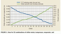
Figure 1 provides performance data for 32 combinations of chiller motor/compressor, evaporator, and condenser. Generally, the better the performance of a chiller (the lower the kilowatts per evaporator ton), the higher the cost. Thus, from the group of chillers in Figure 1, one can select 0.455-kw-per-ton Chiller 1 at minimum cost or 0.395-kw-per-ton Chiller 32 at maximum cost.
For the chillers in Figure 1, the entering-condenser-water temperature is 71°F, flow in the evaporator is 2,400 gpm, condenser flow is 3,000 gpm, and evaporator load is 1,000 tons. These conditions, especially the 71°F entering-condenser-water temperature and 1,000-ton evaporator load, are unlikely to exist in a real system, as explained below.
Plant With Chiller 32 Installed
Figure 2 illustrates the peak-load performance of a plant incorporating Chiller 32. Table 1 provides the nomenclature. The peak site load of 980.4 tons will be used for all of the plants discussed in this article.
The plant incorporating Chiller 32 is at energy equilibrium,3,4 or steady-state condition. Chiller performance is a little better than in Figure 1, primarily because the temperature of the water entering the condenser is less than 71°F. This is because the condenser load is 1,140 tons, below the load of 1,200 tons for which the cooling tower was selected. At a load of 1,200 tons, the capacity of the cooling tower is 104.6 percent. The site load requires Chiller 32 to operate at 100-percent capacity (395 kw) to provide approximately 44°F supply water, with an evaporator load of 1,014 tons. The cooling tower provides less-than-71°F water to the condenser, which results in better chiller performance than given in Figure 1. This is offset a bit by the flow in the bypass, which requires the chiller to provide a little less than 44°F supply water, and an evaporator load of 1,014 tons vs. the 1,000 tons in Figure 1.
The load on the condenser consists of the evaporator load, the compressor heat load, and the cooling-tower-pumping load. The load on the evaporator consists of the site load (980.4 tons) and the primary-and-secondary-pump load. The pump kilowatt heat load is a function of pump efficiency. The secondary-pump heat load is 80.3 percent of 121.8 kw. The chiller-pump efficiency is 81 percent, while the cooling-tower-pump efficiency is 83 percent. The primary, secondary, and cooling-tower pumps are operating at the values shown by:
(P)sec-kw = (2,435 gpm) × (213 ft) × 0.746 kw/hp/(3,960 × 0.803) = 121.8 kw
(P)c-kw = (2,400 gpm) × (48.2 ft) × 0.746 kw/hp/(3,960 × 0.81) = 26.9 kw
(P)t-kw = (3,000 gpm) × (83.8 ft) × 0.746 kw/hp/(3,960 × 0.83) = 57 kw
Page 2 of 5
Performance. Selecting Chiller 32 based on Figure 1 would result in a plant requiring more peak kilowatts than a plant with any of several other of the 31 chillers. Figure 3 provides data minimizing plant kilowatts. The top half of Figure 3 shows the obvious: As chiller kilowatts per ton decreases, refrigerant approach temperature decreases. Chiller 1 has a total approach temperature of about 10°F, while Chiller 32 has an approach temperature of about 4°F; as shown in Figure 1, the lower the approach temperature, the higher the chiller cost.
The bottom half of Figure 3 provides data that significantly affect chiller selection, if the objective is to minimize plant kilowatts per ton of site load and not chiller kilowatts per ton of evaporator load. The bottom half of Figure 3 shows that a number of chillers (Nos. 10, 13, 16, 17, 18, and 24 through 32) have high values of evaporator- and condenser-pressure drop. Chiller 19 has the lowest pressure drop, with Chiller 9 close behind. The cost increase for Chiller 9 is about one-third that for Chiller 32, while the cost increase for Chiller 19 is about half that for Chiller 32. The question is, will Chiller 32, with its high hydraulic-pressure drops, have a plant-kilowatt value better than Chiller 19’s and Chiller 9's? If it will, by how much, and is it worth the cost? We will look at Chiller 9.
Plant With Chiller 9 Installed
Figure 4 shows the plant at energy equilibrium5 with Chiller 9 installed. The plant kilowatts increased from the 665 of Figure 2 to 677. While a mere 12-kw increase may make the additional cost for Chiller 32 difficult to justify, later in this article, we will discuss the issue of cooling-tower selection, which will make the justification much easier.
The conditions in figures 2 and 4 could be estimated with a handheld calculator. The primary and secondary pumping load on the evaporator could be defined as a function of the plant being studied. The cooling tower's response to the condenser load is determined from the manufacturer's program; with one or two iterations, an estimate of the conditions in figures 2 and 4 could be determined. The plant model takes the iterations to an exact balance.
Page 3 of 5
Plant Performance of 32 Chillers
Figure 5 shows that the plants in which chillers 19 and 22 are installed perform about the same as the plants in which chillers 30, 31, and 32 are installed, but cost significantly less. At this point, it seems Chiller 19 is the absolute best choice, with Chiller 9 perhaps the best low-cost choice. However, we have yet to consider part-load performance.6
Part-Load Performance
The top half of Figure 6 shows that Chiller 32 is the most efficient in terms of kilowatts per ton of evaporator load, followed by chillers 19, 9, and 1. The bottom half of Figure 6 shows that as site load and wet-bulb temperature decrease, with a resulting condenser-water-temperature decrease provided by the cooling tower, chillers 9 and 19 perform better with a site load of about 693 tons and below. Note that as the wet-bulb temperature decreases, the condenser-water approach temperature decreases because of the reduced load on the cooling tower. For example, at 60°F wet bulb, the condenser water coming from the cooling tower is 63.38°F, for an approach of 3.38°F. At a wet bulb of 56.7°F, the condenser water coming from the cooling tower is 58.81°F, for an approach of 2.11°F (vs. 4.6°F [70.6 – 66.0]) at peak design.
This indicates the number of calculations occurring within a computer as it iterates to a steady-state condition, a process that, with a handheld calculator, probably is not possible within one engineer’s career. Thus, a computer model is required when evaluating part-load performance.
7°F-Approach Cooling Tower
Figure 7 illustrates the effect of a cooling tower with a 7°F approach temperature. The cooling tower, which was selected for a load of 1,200 tons, has a capacity of 101.5 percent, three cells, and a total of 35 kw of fan power. The top half of Figure 7 shows, as expected, a level of performance lower than that in the top half of Figure 6 for chillers 9, 19, and 32. The bottom half of Figure 7 shows plant performance is about the same for chillers 19 and 32, with Chiller 9 requiring a little more power at peak-load conditions. For site loads of 787 tons and less, the plant with Chiller 32 clearly performs the worst. The cooling tower and chiller pump provide a constant load. As the site load drops, the plant with Chiller 32 becomes less efficient than the plants with chillers 9 and 19, which have less pump load.
Page 4 of 5
Plant With Chiller 9 at Energy Equilibrium
Figure 8 illustrates energy equilibrium for the plant with Chiller 9 and a cooling tower with a 7°F approach temperature.
The figures show significant differences in performance. Chiller 32 is the best-performing plant (0.389 kw per 1,014 tons of evaporator load) according to Figure 2 and the worst-performing according to Figure 5 and the bottom half of Figure 6. Figure 4 shows the Chiller 19 plant at energy equilibrium, with a 0.425-kw-per-ton chiller the performance of which is equal to the performance of Chiller 32 shown in Figure 5. Figure 6 shows that the Chiller 9 and Chiller 19 plants beat the Chiller 32 plant in part-load performance and cost less.
Introducing a cooling tower with a 7°F approach temperature reduced plant kilowatts and increased chiller-motor size in all three plants. The best peak performance (650 kw) was achieved by the Chiller 19 plant, followed closely by the Chiller 32 plant (651 kw). Although the Chiller 9 plant required 664 kw, it represented a significant cost advantage over the Chiller 19 plant when part-load performance was taken into consideration.
With a cooling tower with a 7°F approach temperature, Chiller 19 went from 418 kw to 439 kw, while Chiller 32 went from 395 kw to 415 kw.
Location
Figure 9 shows the operation of a plant similar to the Chiller 19 plant in Kansas City, Mo.; Long Beach, Calif.; and Salt Lake City. The top half gives design wet-bulb conditions, while the bottom half gives plant kilowatts per ton of site load, with the site load the same for each plant. The Kansas City plant can never get to the Salt Lake City plant’s values; if it could, the Salt Lake City plant’s numbers could decrease with the same new equipment and procedures. Design wet-bulb conditions set the limits on plant performance, while location sets the wet-bulb conditions. The issue of multiple-chiller operation is a simple one with a plant model. Adding one or more chillers with a comparable increase in site load and changing the distribution piping and pumping is a very straightforward procedure.
Page 5 of 5
Why model?
A plant model could be of value in commissioning or troubleshooting a plant. The model would show the efficient performance of the plant for any conditions of wet bulb and site load. The first law of thermodynamics would give the real-system site load, evaporator load, and condenser load, which could be checked against the model. The chiller model and cooling-tower model working in balance would provide the plant-efficiency performance for any condition. Having this capability on a laptop computer would be of value, but having a plant model as part of the central monitoring/control system would provide valuable information for operators and owners.
Summary
Hour-by-hour analysis has been suggested for chiller selection,1 a suggestion this author agrees with in terms of the need to perform a mathematical model of a system. However, a model of the plant, including part-load performance, may be a simpler yet still adequate approach.
The monthly or yearly energy consumption of a system could be estimated using the data in the bottom half of Figure 7. Selecting a site load and wet-bulb temperature consistent with the use and location of the plant would increase the accuracy of the energy-use estimate. Defining the hours of operation at each condition could provide an estimate of monthly and/or annual energy consumption of the plant.
References
- Geister, W.R., & Thompson, M. (2009, December). A closer look at chiller ratings. ASHRAE Journal, pp. 22-25, 28-30.
- Hubbard, R.S. (2010, March). Letters. ASHRAE Journal, p. 16.
- Sauer, H.J., Howell, R.H., & Coad, W.J. (2001). Principles of Heating Ventilating and Air Conditioning. Atlanta: American Society of Heating, Refrigerating and Air-Conditioning Engineers.
- Nelson, K.P. (2006, December). 7 upgrades to reduce building electrical demand. ASHRAE Journal, pp. 50-52, 54-57.
- Nelson, K. (2010, March). Central chilled water system modeling. Engineered Systems.
- Schwedler, M. (1998, July). Take it to the limit ...or just halfway? ASHRAE Journal, pp. 32-33, 36-39.
Kirby Nelson, PE, has been involved in the modeling of HVAC systems since the oil embargo of 1973—first as corporate energy manager for Texas Instruments Inc., then as a consultant. Models he has used include DOE-2, E Cube, and models developed on an analog/digital computer, including models of cleanrooms. A life member of the American Society of Heating, Refrigerating and Air-Conditioning Engineers, he has presented numerous papers, led an energy engineering delegation to China, and more recently developed models for district cooling systems, thermal-storage systems, and central plants.
Did you find this article useful? Send comments and suggestions to Executive Editor Scott Arnold at [email protected]. Your feedback is appreciated.
