Fan Selections and Their Energy Impacts, Part 1 of 2
Fans and fan systems can be significant consumers of energy in commercial applications and the greatest consumer in industrial ones. Concerned about underperformance, designers tend to compensate for uncertainties by adding capacity to fans. Oversizing fan systems creates problems that can increase costs and decrease reliability. This article explains how to evaluate fans and fan systems and their impact on operating costs. It does so by examining the criteria most commonly used in fan selection:
- Air-stream characteristics.
- Capacity.
- Pressure.
- Power.
- Efficiency.
- Fan and system curves.
Air-Stream Characteristics
Fan manufacturers’ published ratings for airflow, pressure, and power are based on laboratory conditions using standard cubic feet per minute (scfm) for airflow and 0.075 lb per cubic foot for fan-inlet-air-stream density (corresponding to dry air at 70°F and atmospheric pressure of 29.92 in. Hg). Normally, they can be used for fan selection and evaluation when the difference between standard density and actual site density at a fan inlet is less than 5 percent. This occurs when:
- Fan-inlet temperature is within 30°F of the standard +70°F dry air.
- Fan-inlet pressure is within 12 in. wg of the standard atmospheric pressure of 29.92 in. Hg.
- Fan-inlet-air-stream moisture content is less than 0.02 lb of water per pound of dry air or the dew point is less than 80°F.
- Installation is between 1,000 ft below and 1,000 ft above sea level (asl).
In cases in which at least one of the above parameters is not met, inlet-air-stream density should be corrected to actual conditions (actual cubic feet per minute [acfm]). This is done by multiplying the standard density, airflow, pressure, and power by each parameter’s density factor. The density factors will be equal to the actual inlet density divided by the standard inlet density of 0.075 lb per cubic foot. The density factor (Fρ) for each parameter is estimated as follows:
Density-factor temperature, degrees Fahrenheit:
Fρ(t) = 530 ÷ (460 + Tinlet)
Density-factor pressure, inches water gauge:
Fρ(p) = 407 ÷ (407 + Pinlet)
Density-factor moisture, pounds of water per pound of dry air:
Fρ(m) = (1 + w) ÷ (1 + 1.607w)
where:
w = humidity ratio, pounds of water per pound of dry air
Density-factor elevation, feet above sea level:
Fρ(e) = [1 − (6.73 × 10⁻⁶) × z]5.258
where:
z = elevation, feet
Overall density-correction factor, then, is given by:
Fρ = Fρ(t) × Fρ(p) × Fρ(m) × Fρ(e)
Example 1: Density-factor calculation. For a fan capable of handling 176°F air at an inlet static pressure of –15 in. wg, a humidity ratio of 0.04 lb of water per pound of dry air, and a site elevation of 3,000 ft asl, we will calculate the required density factor and actual air density:
Inlet temperature, 176°F:
Fρ(t) = 530 ÷ (460 + 176) = 0.83
Inlet static pressure, −15 in. wg:
Fρ(p) = (407 + −15) ÷ 407 = 0.96
Inlet moisture, 0.04 lb water per pound dry air:
Fρ(m) = (1 + 0.04) ÷ [1 + (1.607 × 0.04)] = 0.98
Elevation, 3,000 ft asl:
Fρ(e) = [1 – (6.73 × 10–6) × 3,000]5.258 = 0.90
Density factor:
Fρ = 0.83 × 0.96 × 0.98 × 0.90 = 0.70
The actual air-stream density at the fan inlet is the product of the density factor and the standard air density (0.075 lb per cubic foot) and is calculated as:
ρ(actual) = 0.70 × 0.075 lb per cu ft = 0.0525 lb per cu ft
Example 2: Fan performance. If a fan were selected from a manufacturer’s standard catalogued ratings for a volumetric-flow rate of 30,000 acfm, a static pressure of 15 in. wg, 1,910 rpm, and 86 hp, but installed at the above conditions, the operating performance would be:
- Actual volumetric capacity: 30,000 acfm.
- Actual mass-flow capacity: 1,575 lb per minute (30,000 × 0.0525).
- Actual static-pressure delivery: 10.5 in. wg (15 in. wg × 0.70).
- Actual fan-shaft power consumption: 60.2 hp (86 hp × 0.70).
- Actual inlet-air-stream density: 0.0525 lb per cubic foot (0.70 × 0.075).
Key point: With proper definition of inlet-air-stream conditions for density, temperature, pressure, moisture, and elevation, corrections between a fan manufacturer’s published ratings and actual operating conditions can be made to ensure proper fan selection and performance.
Capacity
Fan capacity can be stated in terms of either volumetric-flow rate or mass-flow rate.
Volumetric-flow rate:
- Is the normal basis for fan ratings.
- Normally is stated in cubic feet per minute.
- Represents the actual volumetric-flow capacity of a fan at a given speed and static pressure.
- Is constant for any air-stream density.
Mass-flow rate:
- Normally is stated in pounds per minute.
- Represents the mass-flow capacity of a fan at a given speed, static pressure, and inlet density.
- Is calculated by multiplying volumetric-flow rate by actual air-stream density at a fan’s inlet.
- Varies with changes in air-stream density.
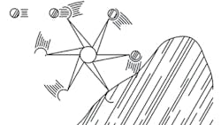
Figure 1 is a simplified illustration of a centrifugal-fan wheel and a substance conveyed by the fan. If each scoop of the fan wheel has a volumetric capacity of 5 cu ft and the speed is a constant 1,000 rpm, the volumetric capacity is 30,000 cfm (5 cu ft per scoop × 6 scoops × 1,000 rpm). The mass-flow rate is:
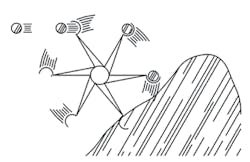
5 cu ft per scoop × 6 scoops × 1,000 rpm × density (pounds per cubic foot) of substance conveyed
Assuming the substance is air at standard conditions and standard density of 0.075 lb per cubic foot, the mass delivery is 2,250 lb per minute (30,000 cfm × 0.075 lb per cu ft).
Assuming the substance is air at the non-standard conditions in examples 1 and 2 with a density of 0.0525 lb per cubic foot, the mass delivery is 1,575 lb per minute (30,000 cfm × 0.0525 lb per cu ft).
If the fan system must maintain a minimum mass-flow rate of 2,250 lb per minute, then the required actual volumetric-flow rate is 42,857 cfm (2,250 lb per min ÷ 0.0525 lb per cu ft) and the fan should be selected on the volumetric basis of 42,857 acfm.
Key point: At constant speed, a fan will deliver a constant volumetric-flow rate and a variable mass-flow rate, with the mass-flow rate varying directly with the density factor, or the ratio of actual density to standard density.
Pressure
In air-moving applications, the most common pressure is static pressure. Still, for the proper selection and operation of fans, one must have a basic understanding of all pressures:
- Total pressure (TP).
- Velocity pressure (VP).
- Static pressure (SP).
- Fan static pressure (FSP).
- Fan velocity pressure (FVP).
- Fan total pressure (FTP).
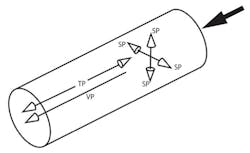
Figure 2 shows total-, static-, and velocity-pressure components for a short section of ductwork. Total pressure is parallel to and measured in the direction of flow. Velocity pressure is parallel to the direction of flow and can be measured only indirectly as the difference between total pressure and static pressure. Static pressure is exerted equally in all directions and measured perpendicularly to the direction of flow.
Total pressure. Total pressure is the algebraic sum of kinetic energy (velocity pressure) and potential energy (static pressure) at any point in a system. Thus, total pressure represents the total energy at the point of measurement of fluid flow:
TP = VP + SP
Total pressure can be positive or negative, depending on the measurement location.
Velocity pressure. Velocity pressure is kinetic energy in the direction of flow that causes a fluid at rest to flow:
VP = TP − SP
VP = (V ÷ 1,097)2 × ρ(actual)
therefore:
VP = (V ÷ 4,005)2 × Fρ
Velocity pressure is mutually convertible with static pressure. It always is positive, regardless of its measurement location.
Static pressure. Static pressure is potential energy exerted in all directions by a fluid:
SP = TP − VP
Static pressure is mutually convertible with velocity pressure. It can be positive or negative, depending on the measurement location.
Fan total pressure vs. total pressure. While total pressure is the sum of velocity pressure and static pressure, fan total pressure is the increase in total pressure through or across a fan and represents the total work delivered by the fan. As defined in Air Movement and Control Association (AMCA) International standards, fan total pressure normally is not used for fan-rating purposes (this is by custom, not because of any deficiency in the rating technique). However, an understanding of fan total pressure is important for proper selection and field measurement of fans and fan systems. Fan total pressure is expressed as:
FTP = TPfan outlet − TPfan inlet
FTP = (SPoutlet + VPoutlet) − (SPinlet + VPinlet)
When fan-inlet velocity pressure and fan-outlet velocity pressure are the same, the pressures cancel each other, and the fan-total-pressure calculation is simplified to:
FTP = SPoutlet − SPinlet
In this case, fan total pressure simply is the difference between fan-inlet static pressure and fan-outlet static pressure. When a fan is specified on the basis of summing inlet and outlet static pressures (static-pressure rise across the fan), the fan rating is on the fan-total-pressure basis.
Fan velocity pressure. AMCA International defines fan velocity pressure as velocity pressure based on the average velocity at a fan’s discharge. The average velocity at a fan’s discharge typically is calculated as fan outlet velocity divided by fan outlet area (square feet). For standard air, this is:
FVP = (fan outlet velocity ÷ 4,005)2
Fan static pressure vs. static pressure. Fan static pressure as defined by AMCA International is the basis for most published fan ratings today. While static pressure is the difference between total pressure and velocity pressure, fan static pressure is defined as fan total pressure minus fan velocity pressure:
FSP = FTP − FVP
FSP = (TPfan outlet − TPfan inlet) − VPfan outlet
FSP = (SPoutlet + VPoutlet) − (SPinlet + VPinlet) − VPoutlet
Because the outlet velocity pressures are identical and cancel each other:
FSP = SPoutlet − SPinlet − VPinlet
or, more commonly:
FSP = SPoutlet − TPinlet
However, it is not uncommon to find the static pressure used by system designers for fan selection calculated simply as:
SPoutlet − SPinlet
Often in these cases, the fan is oversized by the inlet-velocity-pressure energy component, resulting in excessive energy consumption.
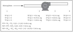
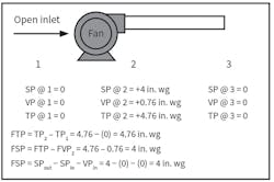
When static pressure used for fan sizing is calculated in this manner, a fan cannot perform exactly on the fan curve because of the velocity pressure at the fan inlet normally not accounted for by the fan manufacturer. Figures 3 and 4 present examples of how to calculate fan pressure for various fan configurations.
Key point: For optimum energy utilization and fan performance, follow the fan-static-pressure calculations issued by AMCA International.
Example 3: Fan pressure—actual and equivalent. Actual fan pressure normally is defined as the pressure a fan delivers at actual operating conditions, while equivalent fan pressure normally is defined as the pressure a fan delivers at standard conditions (0.075-lb-per-cubic-foot air-stream density).
Because fan manufacturers’ catalogue ratings are based on standard conditions, it is important to make sure a fan is selected to achieve its design pressure at actual operating conditions.
Referring to examples 1 and 2, a fan with a catalogued fan static pressure of 15 in. wg will produce a fan static pressure of only 10.5 in. wg at actual operating conditions. If 15-in.-wg fan static pressure is required at actual operating conditions, a fan must be selected for a catalogued fan static pressure of 21.4 in. wg (15 ÷ 0.7). Normally, the designer would note a requirement of 15 in. wg at standard conditions and 21.4 in. wg at actual operating conditions.
So far, we have discussed air-stream characteristics, capacity, and pressure. Next month, in Part 2 of this two-part article, we will discuss fan power, fan efficiency, and fan-system curves.
Khalil Kairouz, PhD, PE, is an associate vice president for Carollo Engineers Inc., a consulting firm specializing in water and wastewater treatment. He has bachelor’s and master’s degrees in mechanical engineering from the University of Louisiana at Lafayette and a doctorate from Claremont Graduate University. He has taught in the mechanical-engineering departments of Loyola Marymount University and California State University. Dale Price is president of M&P Air Components Inc., a company specializing in ventilation and air-distribution equipment. He has a bachelor’s degree is mechanical engineering and is an active member of an American Industrial Hygiene Association task force on fan efficiency. He has taught numerous training sessions on fan systems and their effects to employees of state and federal agencies and private industries.
Did you find this article useful? Send comments and suggestions to Executive Editor Scott Arnold at [email protected].