By NICHOLAS H. DES CHAMPS, Ph.D., PE, Fellow ASHRAE
Des Champs Technologies LLC
Natural Bridge Station, VA
When using a toilet to get rid of human waste or a sink to wash vegetables, the discarded product ends up in the same sewer line prior to its destination, the septic tank or sewage treatment plant. Obviously, you would not want the gases from the toilets to penetrate the kitchen where food is being prepared so an airtight seal is required between the appliances and the sewer line.
Since the end of the 19th century, P-Traps have been used successfully for this purpose, for each incident enough water flows through the trap to move the waste from the source to the sewer while leaving water within the trap as a seal against air flow. There are problems associated with the P-Trap when used in disposal systems, such as dry-out or freezing, but the benefits outweigh them.
Since P-Traps seal against air leakage, they were the natural solution to prevent air leaking in the condensate drains of early 1900s air conditioning units. As air conditioning caught on in the 1950s, P-Traps were the standard that every contractor field designed, and installed, even if it was unknown to them whether the drain pan was at negative or positive pressure, or even at what level of pressure. It is still that way today. Air conditioning units are shipped from the factory to the job site without a condensate drain trap. The AC equipment is set on the slab, floor, or curb and it is the mechanical contractor’s job to install a P-Trap. There is a major difference between using P-Traps on sanitary applications and condensate removal from an AC unit and that is the latter has a pressure within the drain pain.
Plumbing Codes
Presently, most plumbing codes call for the use of a P-Trap on all appliances that are connected to a sanitary sewer. The only code requirements for drain lines removing condensate from HVAC equipment are:
a) for the installation of a trap in accordance with the unit manufacturer’s installation and operating instructions;
b) that the drain lines slope toward the final drainage point at a rate of 1/8 inch per foot.
The information that the engineer or contractor requires to properly design and install an HVAC condensate drain line with a standard P-Trap is:
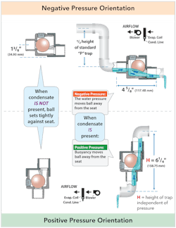
1. Does the fan draw through the cooling coil (negative drain pan pressure) or blow through the cooling coil (positive drain pan pressure)?;
2. The maximum operating pressure across the trap, i.e. drain pan compartment to ambient;
3. Maximum gallons of condensate per hour, required to size the drainpipe;
4. The Greatest interval of time that condensate will not be produced (to determine the depth of trap to prevent dry out);
5. Inches per month water evaporation rate for the geographic area;
6. Will the drain piping require a vent pipe immediately downstream of the condensate trap?;
7. Design guide for P-Traps;
8. Depth of P-Trap to insure a water seal during the entire 365 days.
Rate at Which Water Evaporates within a P-Trap
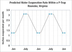
Tests by the author indicate water will evaporate at a rate of approximately 2.2 inches per month from late spring through early fall. It does not make a difference if the drainpipe is ¾-inch in diameter or 1 ½-inch, or from a 20’ x 40’ swimming pool, the water evaporates at an average rate of 2.2 inches in height per month. The readings were taken near Roanoke, VA.
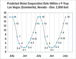
If there is a drain line of considerable length that has pockets of water remaining in the line after condensate ceases, then the evaporation rate in a P-Trap could be as low as 1.1 inches per month. In arid regions the evaporation rate will be higher, up to 3 inches per month. For example, if you have a residence in Las Vegas (Figure 4), and you are gone for six weeks, the toilet will have dried out by the time you return. Basically, dry P-Traps waste considerable energy as will be presented in the following paragraphs.
Design Options
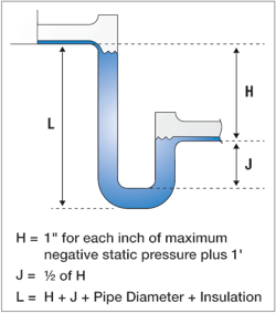
A typical P-Trap design for draw-through equipment is shown in Figure 1. For a system operating at 1½ inches of negative pressure, J will be 1¼ inches of height, which with an evaporation rate of 2 inches per month the seal will be lost after just two weeks of noncondensing operation! This is good reason to believe that P-Traps in most of the country operate dry over 50% of the time.
Even worse is what has almost become standard for P-Traps in residential applications, a ¾” bent PVC tube as shown in Figure 2a. With the trap set level and filled with water a test was run to see at what pressure the trap would cease to seal against air flow. The pressure was gradually decreased from zero to the point where the water began to gurgle within the trap. For the inline trap a pressure of - ⁵⁄₈” WC caused the air seal to break. For the trap shown in Figure 2b it took 2 days of evaporation before the seal broke at -⁵⁄₈” WC. Both tests were run at 75°F and 50%RH.
The standard design for a P-Trap, as shown in Figure 2, does not fully take into consideration the evaporation of water from the trap over time. As already mentioned, a trap must seal against air leakage all year. For it to do that, two things must be taken into consideration: First, it must be designed with a water reservoir sufficiently deep or large to ensure the water seal is not evaporated away. Second, the water reservoir must be protected from freezing. Therefore, instead of H being equal to 1” for each inch of maximum negative static pressure plus 1”, it should be 1” for each inch of maximum negative static pressure plus 1” + (N x E), where N = number of months without condensate being formed and E = the average evaporation rate of water in inches per month during the non-condensing period.
As an example, take an AC unit in Roanoke, VA, operating at 1-inch negative pressure and using a ¾ diameter pipe, that is typically cooling from May through September, or five months of the year. That’s seven months of no condensate formation. Referring to Figure 3, from October through April the average evaporation rate of the condensate is about 1.5 inches per month. Using the revised formula:
H = 1 +1 =2
J = ½ H + evaporation = 1 + 7 x 1.5 = 10.5
Therefore, the height of the trap L = H + J + pipe diameter + insulation, or ...
L = 2 + 10.5 +1 + 0 = 13.5 inches
Even at 1 inch per month evaporation, the trap would require an L of 10 inches.
This may seem unrealistic so you might want to check a residential trap near the end of April before cooling season, anywhere except in Florida, and see if it has a water seal.
Leakage Rate of Air
Let's take a look at the leakage rate of air through a condensate drain line with a dry P-Trap.
- v = velocity of air within drain line (ft/sec)
- p = loss of pressure due to flow through the pipes (ounces/in2)
- d = inside diameter of condensate drainpipe (in.)
- L = length of condensate drainpipe in feet (ft)
- Qi = volumetric flow per trap (ft³/min.)
- 25,000 = unit conversion factor
For p = 2 inches WC, d = 1.5 inches, and L = 10 feet, the CFM lost to the environment is 48.4 CFM.
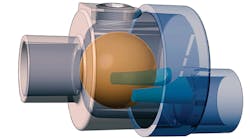
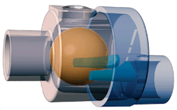
Now let's look at the leakage rate of air through the same drain line as above but with a trap designed specifically for HVAC equipment as shown in Figure 5.
The leakage rate is 0.060 CFM. This leakage rate exists anytime during the year that the fans are operating.
Stop Wasting Energy
Energy wasted by P-Traps is estimated by the author to be on the order of $3 billion per year in the U.S. alone. Sealing this leakage should be seriously considered by energy-conscious owners, specifying engineers, installing contractors, and government officials. The quickest, easiest, and most cost-effective way to reduce the wasted energy is to replace the installed P-Traps with traps that do not require water as the means of sealing against air leakage (i.e., a trap that seals with air pressure).
Not only would the HVAC Air-Trap be saving “tons” on energy, but would essentially eliminate the eight issues inherent with P-Traps:
- Freezing and breaking;
- P-Trap Dry-outs;
- Sludge formation in bottom of “U” bend;
- Geyser effect of air rushing into drain pan and spraying water or causing overflow of drain pan;
- Mold, mildew, and undesirable bacteria forming in the cooling-coil compartment;
- Air leakage;
- Height requirement for trap to function properly (e.g., the Air-Trap is less than ½ in. tall);
- Incorrectly designed and installed.
Owners would really appreciate saving the energy and not dealing with the eight issues resulting from P-Traps as well as the consequences of malfunctioning, especially water running down their walls when the AC units start-up in the spring, as the author has witnessed on numerous occasions.
The HVAC Air-Traps come in all sizes and shapes to cover essentially any condensate requirement. The P and N Series for commercial applications, the RLC for residential and light commercial, the FCN series for residential, hotels, apartment houses, and the PLP for positive pressure application where pressures up to 40 inches WC or more can be accommodated in a height of less than 3 inches.
Please visit www.deschampstechnologies.com for more information on air pressure-activated condensate traps.

