Though we have figured out how to build strong tall structures and safely move people inside, challenges of heating and cooling, of moving fresh water in and dirty water out, and of providing fire protection and electricity persist. These are made all the more complicated by a need to defy gravity. This article discusses basics of pipe-riser design and performance, identifies key considerations regarding the use of expansion joints in pipe risers, and explains codes and standards governing the guidance and support of risers.
Last month, Part 1 of this article discussed thermal-expansion basics, riser spring supports, and pressure and the height of a water column. This month, the article concludes with discussion of riser structural-stability considerations, pipe guides, bellows expansion joints, flexible-hose-and-braid-loop expansion joints, and more.
Riser Structural-Stability Considerations
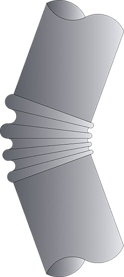
Column buckling is a familiar failure mode. If a long, slender bar is subjected to axial forces at each end, it will bow out (Figure 8). This is a function of the material strength, cross-section dimensions, and length of the bar. A pipe behaves like this, too: Axial forces applied at each end will make it bow out. This can be especially pronounced with small-diameter copper pipe.
FIGURE 8. Column buckling of a double-pinned bar (or pipe).
Although most of this bowing is elastic, meaning pipe goes back to its original shape after loads are removed, it can be a problem if pipe bows beyond the elastic limit of its material. Column buckling also can be a problem with bellows expansion joints. If the two ends of a bellows are not within offset movement limits, permanent damage will result.
Pipe must remain aligned as it travels through a building. This is the purpose of pipe guides, which restrict pipe movement to the axial direction and essentially make pipe more rigid. Guides divide pipe into shorter, stiffer sections.
The spacing of pipe guides is dictated by classic column-buckling equations, called the Euler buckling equations. Assuming pipe is pinned on either end, the equation looks like this:
Pcr= (π2 EI) ÷ l2 (1)
where:
Pcr = maximum column load (lb) to initiate buckling
E = material elastic modulus (psi)
I = cross-section moment of inertia (in.4)
l = column length (in.)
This is the theoretical load limit for a column with the ends free to rotate and loads applied along the axis. Note the weights of the pipe and water are not considered here. Euler buckling is an important consideration when bellows expansion joints are chosen for a piping system, especially risers, as forces are acting along the pipe’s longitudinal axis.
If pipe is fixed at one end (Figure 9), the critical load is:
Pcr= (π2 EI) ÷ (4l2) (2)
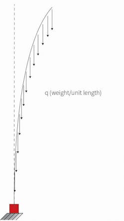
FIGURE 10. Buckling of a vertical fixed support column or pipe under its weight.
What happens when a pipe is turned up on its end? Gravity. The weight of the pipe and the media inside now come into play. A riser pipe theoretically can collapse under its own weight (Figure 10). The critical load on a vertical pipe with the end fixed is:
(ql)cr= 7.837EI ÷ l2 (3)
where:
(ql)cr = maximum column load (lb) to initiate buckling
Using 4-in. pipe as an example and solving for the length with (ql)cr equal to 1.34 lb per inch, the maximum length a vertical 4-in. Schedule 40 carbon-steel pipe can be before becoming unstable is about 90 ft. For comparison, a 4-in. Type K copper riser will become unstable at about 64 ft. This also is the equation that determines the maximum height of a tree (neglecting the branches and assuming a prismatic trunk).
Next, consider a riser having an external force like a bellows pressure thrust and spring force. A riser pipe under an external load subject to the weight of the pipe wall and media inside will have a critical load of:
Pcr= (π2 EI) ÷ (4l2) − 0.3ql (4)
where:
Pcr = maximum column load (lb) to initiate buckling
E = material elastic modulus (psi)
I = cross-section moment of inertia (in.4)
l = column length (in.)
q = weight per inch of pipe, insulation, and contents (lb per in.)
This equation assumes the end of the pipe is fixed and cannot rotate, the pipe has a constant cross section (same size all of the way up), and the weight is distributed equally. The critical load is reduced by 30 percent of the column weight. Note the critical load can be negative, meaning the top end support must be in tension to prevent buckling.
The previous examples and the hydrostatic-pressure explanation are important for guide spacing in risers with different types of expansion joints. Let’s first consider a bellows expansion joint in a tall riser. How would we determine the pipe-guide spacing for this type of installation?
What Are Pipe Guides?
Pipe guides are devices that restrict pipe to axial motion. As a result, pipe is more rigid and will not bow or collapse. The closer guides are placed along a pipe, the greater the amount of axial loading before the pipe becomes unstable.
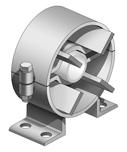
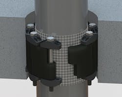
Guides commonly used for HVAC and plumbing systems are either finned or sliding. Finned, or “spider,” guides (Figure 11a) have fins fixed to pipe and travel through a ring secured to a building’s structure. These guides typically are found on small-diameter pipe and used where lateral loads are expected to be relatively small compared with pipe-anchor loads. In horizontal applications, these guides are not intended to take the place of hangers, so a clevis or roller support is required in the vicinity of a guide to hold the weight of the pipe.
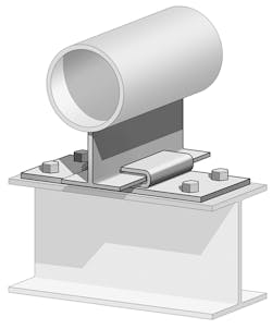
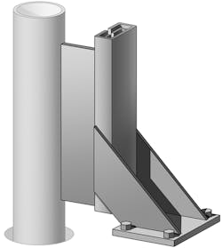
A more robust guide that also can function as a support is the sliding guide (Figure 11b). This device has a sliding bar that is welded to pipe, with a base secured to the structure. The base has a Teflon, graphite, or elastomeric pad to reduce friction. This type of guide can handle greater lateral loads and typically is used on larger-diameter HVAC pipe and process piping. A version of the sliding guide adapted to risers incorporates an elastomer cushion between the slide and base to dampen noise and vibration from the pipe sliding against slab penetrations (Figure 11c).
FIGURE 11d. Modular riser guide in slab penetration.
The most compact guide configuration consists of an elastomeric seal assembly within a slab penetration (Figure 11d). Such a guide takes up no floor space in a riser chase.
Use of Guides With Bellows Expansion Joints
According to Expansion Joint Manufacturers Association (EJMA) standards, guides are required no more than four pipe diameters from a bellows expansion joint. The space between the first and second guides should be no more than 14 pipe diameters, with subsequent guides spaced at intervals dictated by the Euler buckling equation for a half-pinned column. When guides are placed according to EJMA guidelines, pipe is subdivided into rigid sections that (theoretically) should not buckle under a known end load.
Guides used with bellows expansion joints serve two purposes: to keep pipes from buckling and to keep bellows from buckling (Figure 12). EJMA standards assume a horizontal pipe, and the buckling formula used divides the calculated length in half. For example, a 4-in. steel pipe with bellows expansion joint under 158 psi of pressure requires intermediate guide spacing of 30 ft. The pipe is assumed to be horizontal, so the weight of the pipe and media is not considered in EJMA calculations.
Typically, model codes require risers to be supported roughly at every floor. This usually is accomplished with riser clamps. As described in Part 1 of this article, riser clamps can move upward and lose contact with a floor slab, meaning the support is not doing its job and all of the load is borne by the anchor. In such a case, codes may have been followed, but the anchor may not be designed for the weight of the pipe, insulation, and contents, as well as any force generated by the expansion joints.
Bellows Expansion Joints in Risers
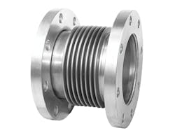
FIGURE 14. Internally pressurized bellows.
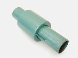
The use of bellows expansion joints in risers is common, mostly because of their compact shape (figures 13 and 14). They take up very little space perpendicularly to pipe axes and, thus, fit nicely in crowded pipe chases; however, they need to be guided. Bellows produce large anchor loads. This may be a necessary trade-off, as space in pipe chases can be at a premium.
Vertical pipes are subject to variations in hydrostatic pressure. These variations are simple to calculate, being the difference between the system operating pressure at the top of a riser and the height divided by 2.31 added to the system pressure at the bottom of the riser. Using our 500-ft riser (Part 1) with a system pressure of 50 psi as an example, pressure is 50 psi at the top of the riser and 267 psi at the bottom. This difference in pressure is critical in calculating anchor loads for bellows expansion joints.
A bellows expansion joint installed near the bottom of a tall riser must be rated for the pressure there. In the previous example, a 150-psi expansion joint would be fine for the top section of the riser, but a higher-pressure expansion joint would be required near the bottom.
What about anchor loads? Bellows expansion joints create reaction forces based on two characteristics of the bellows: the spring rate and the effective area. The spring rate simply is the amount of force required to compress or extend bellows 1 in. If a bellows has a 500-lb-per-inch spring rate, it will exert 500 lb on each anchor for every inch of movement. If the bellows is compressed 1.5 in., the spring force will be 750 lb on each anchor.
Pressure thrust may not be quite as straightforward. An expansion joint is the most flexible part of a piping system. A bellows under pressure wants to stretch back to its original shape, which is a tube. If left unrestrained, a bellows under pressure will extend past its rated movement. This is why control rods and anchors generally are required for a bellows expansion joint. The amount of force exerted on anchors or control rods by a bellows is simple to calculate, being the pressure multiplied by the bellows effective area.
What exactly is bellows effective area? It is the inside area of a bellows, the average of the largest and smallest convolution diameters (also known as the mean diameter). It is provided by bellows manufacturers.
Using our 500-ft riser as an example, with a system operating pressure of 50 psi and a 4-in. pipe, a 4-in. bellows expansion joint at the top will exert on each anchor a pressure thrust (PAE) of:
AE× P
36 sq in. × 50 psi = 1,800 lb
where:
AE = bellows effective area (from manufacturer) (sq in.)
P = operating pressure (psi)
If we split the riser and locate an expansion joint at the midpoint, the pressure used to calculate thrust force will be 50 psi added to the height of the water column above the expansion joint (about 250 ft):
P = 50 psi + 250 ft × 0.43 psi per ft = 158 psi
PAE= 36 sq in. × 158 psi = 5,688 lb
Now, let’s add in the spring force. The riser will move 2.45 in. between each set of anchors. If the spring rate of the bellows is 200 lb per inch:
spring force = spring rate × movement
spring force = 200 lb per in. × 2.45 in. = 490 lb
Friction from pipe supports can be assumed to be very small for a riser and is not factored into these calculations. The total bellows force on the anchors is:
Top: 1,800 lb + 490 lb = 2,290 lb
Bottom: 5,688 lb + 490 lb = 6,178 lb
To get a complete picture, the weight of the pipe, water, and insulation must be added to the bellows anchor loads. The lower bellows forces act upward and the upper bellows forces act downward on the middle riser anchor. It is important to keep track of not only the magnitude of the forces acting on an anchor, but the direction. The anchor is carrying the weight of the pipe and water above. The intermediate anchor loading is more complicated, if the expansion joint is centered between the anchors.
We now have a situation similar to critical loading for a riser under its own weight with an external force. If we look at our critical-load equation (Equation 4) with pipe weight:
Pcr= ([π2 EI] ÷ [4l2]) − 0.3 ql
If we solve for length using a Pcr of 6,178 lb, the guides will require spacing at 23-ft intervals, or maybe every other story.
In the case of a copper riser, more guides would be required. The bellows forces would be roughly equal, as would the hydrostatic pressures. If the bottom half of the riser were considered, the only difference would be the material and cross-sectional properties of the copper pipe. In the case of our 4-in. riser, the material and sectional properties are:
E = 17,000,000 psi (elastic modulus for copper)
I = 3.35 in.4 (Type K copper)
Now, the required guide spacing is 12.5 ft, or maybe every story.
Flexible-Hose-and-Braid-Loop Expansion Joints in Risers
The only way to truly limit the amount of movement in a riser is by anchoring the riser at various levels and installing an expansion joint between each anchor pair.
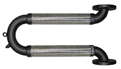
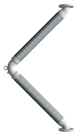
Hose-and-braid expansion joints are another option for risers. Hose-and-braid expansion joints typically are constructed of two pieces of corrugated metal hose wrapped by metal braid. The joint may be fabricated in a “U” or a “V” shape, which provides movement in all directions. Like the other expansion-joint systems, hose-and-braid expansion joints are life-of-building products. Once installed, they require neither maintenance nor inspection.
Hose-and-braid expansion joints offer several advantages over bellows and spring supports:
- Because of the hose-and-braid configuration and the braid preventing the hose from expanding, there is no pressure-thrust component.
- Hose-and-braid expansion joints can be designed for operating pressures commonly found in HVAC and plumbing-system pipe sizes.
- Hose-and-braid sections are very flexible. The only anchor forces generated by these expansion joints can be attributed to the spring forces of the hose and braid, which, for many pipe sizes, typically are less than 100 lb. The only other load on the anchor will be the weight of the full riser.
- Hose-and-braid expansion joints can handle offsets in risers much better than bellows expansion joints.
Figures 15 and 16 show examples of hose-and-braid expansion joints commonly used in risers.
The disadvantage of hose-and-braid expansion joints concerns space requirements. Bellows expansion joints fit nicely in crowded pipe chases, while hose-and-braid expansion joints stick out. This can be accommodated by mounting loops horizontally in a ceiling chase.
Hose-and-braid expansion joints subject risers to small reaction forces, so the bottom half of a riser between anchors may be considered a free-standing length of pipe, similar to Figure 10. This configuration follows a variation of Equation 3 for the portion of riser below the expansion joint:
ql = 7.837EI ÷ l2
The term q is known, so length for column stability (and guide spacing) can be determined by solving for length l. Going back to the example of a 500-ft 4-in. Schedule 40 pipe with hose-and-braid connector in the center, the lower half would be subject to conditions similar to those of a 250-ft riser with fixed bottom. The required guide spacing would be 10.6 ft. For Type K copper, the required guide spacing would be 4.1 ft.
For the portion of pipe above the loop, one guide at the expansion joint would be adequate. In this case, gravity would be working in a favorable direction.
Practical Considerations
How often are guides placed at every other story—let alone at every story—in a high-rise? Almost never. Why, then, do we not see numerous risers collapsing? The answer may be simple: There already are guides in the form of round slab penetrations at every floor. These allow axial movement and restrict lateral movement. Guide placement would be critical in an open chase, where pipes are routed through a single large floor penetration at each level.
Additionally, most risers have takeoffs or runouts at each floor. If hard-piped to equipment in the vicinity of the riser, these can provide additional lateral support to the riser.
Recalling our example of 4-in. steel pipe, EJMA guidelines do not cover the case of a vertical pipe with zero loading (like hose and braid). For the bellows loading in our example, they recommend 31-ft spacing (about every three stories). This author has observed exactly zero riser installations that comply with EJMA guidelines for guide spacing and has yet to see a collapsed pipe riser.
In reality, pipes very well may be bowing elastically, but nobody can see it. It is a case of “out of sight, out of mind.” After all, how many architects design windows on pipe-chase walls? What’s more, how many tenants care enough to observe their risers?
Conclusion
Utilities have to be distributed to all levels of tall buildings. Assuredly, with long vertical pipes, gravity always will act down. Building-system designers should be aware of the forces at play. The petroleum industry is well aware of design considerations for tall, flexible risers through experience with offshore drilling rigs. As we build taller structures, the architect/engineer/contractor community must be aware of similar issues for conditions above the surface.
References
Sparks, C.P. (2007). Fundamentals of marine riser mechanics: Basic principles and simplified analyses. Tulsa, OK: PennWell Corp.
Gere, J.M., & Timoshenko, S. (1961). Theory of elastic stability. New York, NY: McGraw-Hill.
Marty Rogin, PE, is engineering manager for The Metraflex Co. His 29 years in the field have taken him from the edge of space down to the bedrock of our infrastructure systems and several interesting places in between. He is a licensed professional engineer in 13 states and has degrees in engineering mechanics and aerospace engineering.
Did you find this article useful? Send comments and suggestions to Executive Editor Scott Arnold at [email protected].
