In building services and process piping systems, changes in temperature, load, and other operating characteristics cause movement, or deflection, which piping must be able to accommodate to prevent stress that can lead to piping and equipment damage or even threaten the structural integrity of the building itself. Engineers designing and specifying pipe systems use a variety of techniques to handle deflection, with methodologies varying according to the situation.
This article discusses the use of grooved mechanical piping and flexible couplings to accommodate deflection.
Deflection Capabilities of Grooved Piping
There are two types of grooved mechanical couplings: rigid and flexible. Rigid pipe couplings mechanically resist linear and angular movement of pipe at a joint, while flexible pipe couplings permit a controlled amount of linear and angular movement.
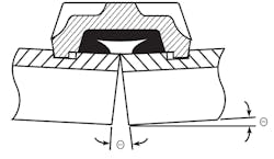
Flexible couplings allow movement of pipe because the dimensions of the coupling key are narrower than the groove in the pipe, providing room for the coupling key to move within the pipe groove. Additionally, the width of the flexible-coupling housing allows for pipe-end separation, leaving room for controlled linear and angular movement. The coupling remains a self-restrained joint, and the pressure-responsive gasket design provides positive sealing, even when pipe is deflected.
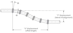
Flexible grooved couplings permit up to several degrees of pipe deflection at a joint (Figure 1), depending on coupling style and size and the type of groove. Precise figures for angular-deflection allowance can be found in manufacturers’ published performance data.
Static Deflection
Two common situations calling for static deflection—that is, pipe staying in the deflected position once installed—are building curvature and pipe-to-equipment misalignment.
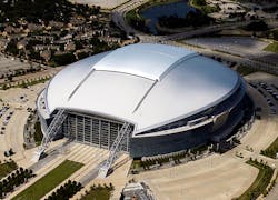
Building curvature. Oval- and ring-shaped buildings, such as stadiums, long have challenged engineers. Parabolic-shaped buildings—the Aria Resort & Casino and Vdara Hotel & Spa in Las Vegas, for example—present the same challenges, but on a smaller scale. Industrial designers face similar issues with structures such as tailing ponds.
Piping systems installed on a continuous but slow curve historically have relied on specially mitered weld fittings, which are difficult to fabricate and can be quite costly.
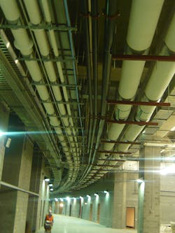
In the case of stadiums, grooved systems can be seen in the concourses of Yankee Stadium in New York City, AT&T Stadium in Arlington, Texas (photos A1 and A2), Marlins Park in Miami, and Sports Authority Field at Mile High in Denver, among many others.
To accommodate a slight deflection at joints, flexible grooved couplings are installed as often as necessary. To minimize hanger requirements, rigid couplings are used except where flexible couplings are needed to provide deflection capability. To calculate the total number of flexible couplings required, divide the total angle of the curvature by the degrees of angular deflection provided by the flexible coupling to be used.
Flexible grooved couplings offer several advantages for handling piping-system curvature. Unlike with welding, no fittings are required, which reduces costs, along with fabrication and installation time. Systems designed to accommodate more deflection than what the curvature calls for may be able to handle other types of movement, such as thermal expansion and contraction and differential settlement.
Equipment misalignment. Pump headers and other large piping sections often are prefabricated to save time and move labor into the controlled environment of a fabrication shop. When hanging and connecting prefabricated pieces to equipment in the field, there may be slight misalignments attributable to fabrication tolerances. Such misalignment is a common occurrence in mechanical rooms. Outside of the HVAC industry, this issue often arises when connecting skid-mounted units to fixed piping, such as in water-treatment facilities employing reverse-osmosis skids.
A number of tactics are employed to handle misalignment on site: rework of piping, adjustment of hangers, forcing pieces into alignment, and use of vibration-attenuation devices to take up lateral offset. Although the former is the preferred method, the latter often are employed as time- and cost-saving measures. These methods can, of course, introduce stress into a piping system and equipment connections. Use of vibration-attenuation devices to handle misalignment can damage equipment; many manufacturers explicitly state their devices are not designed for such applications.
Some engineers and contractors anticipate misalignment and build flexibility into systems. This can be accomplished through the use of flexible grooved couplings. A common misconception of flexible couplings is that a single coupling can be used to accommodate a lateral offset. In reality, at least two flexible grooved couplings must be used to accommodate a centerline offset between two connection points. As such, the proper way to accommodate misalignment is with two flexible grooved couplings and a short pipe spool between them (Figure 2). To compute the required pipe-spool length, divide the anticipated amount of misalignment by the coupling’s deflection-from-centerline capability, taking into account any required design factors. If the length of the spool piece is too large or more movement is required, additional pairs of couplings can be utilized to achieve a greater amount of movement in the same area.
This method simplifies mechanical-room builds, as contractors often use grooved couplings to join mechanical piping. In fact, configurations of three flexible grooved couplings frequently are used for pump connections, as studies have shown the couplings are able to attenuate vibration better than flex connectors. Unlike those devices, the couplings can both isolate vibration and accommodate misalignment, and they do not require regular inspection and maintenance. Designing in anticipation of misalignment can reduce instances of field adjustments and forced alignment, resulting in more reliable, stress-free operation.
Dynamic Deflection
Dynamic deflection, or movement occurring during system operation, may occur gradually, as in the case of differential settlement and building creep, infrequently, as in the case of thermal movement, or frequently, as in the case of building sway.
Differential settlement. Deflection of piping systems can occur because of uneven settlement, particularly when an addition is made to an existing structure. In the case of larger facilities built in segments, including those constructed for seismic-stress relief, the sections typically are permitted to move independently. A newer structure or certain segments of the same structure—those that weigh more, for example—can settle at a greater rate, so flexibility must be designed into piping systems crossing structures or segments.
Often, this flexibility is achieved by building in some sort of geometry to allow pipe to bend, similarly to an expansion loop. Some engineers make use of mechanical couplings, such as bolted sleeve-type couplings, to accommodate gradual deflection, while others specify flexible hoses.
Utilizing geometry in a piping system requires more components and pipe and, thus, space than do other methods. Bolted sleeve-type couplings are not self-restrained, so external harnesses or anchors must be added on both sides of the joint to prevent the pipe from pulling out of the coupling. Additionally, this type of joint may require regular tightening, making it a maintenance item. As for flexible hoses, pressure limitations may prevent use in some applications.
With the grooved method, differential settlement is addressed by using an even number of flexible couplings and permitting intermediate pipe to toggle as movement occurs (Figure 3). The objective in designing for settlement is to achieve the required displacement using the fewest couplings. Because of symmetry around a transition point, the point of inflection is a pipe spool, not a coupling. Number of couplings and pipe-spool length are two variables that can be altered to obtain desired misalignment.
To calculate the number of couplings and the pipe-spool lengths required, determine the maximum amount of lateral misalignment caused by settlement (Y displacement) and the space between fixed connection points in which to make a transition (X displacement). The mathematical formula for Y displacement is:
where:
L = length of pipe spool
a = half the design pipe-end separation for the coupling to be used
n = the total number of couplings to be used
l = n/2
The mathematical formula for X displacement is:
As displacement lengths are known, finding the necessary number of couplings and pipe-spool lengths is a trial-and-error process. For convenience, some manufacturers publish tables that can be used to determine the number of flexible couplings and pipe-spool lengths required to obtain lateral misalignment (Y displacement) within a maximum offset length (X displacement).
Compared with utilizing geometry within a piping system, the grooved method allows for inline deflection, which takes up much less space. Although flexible grooved couplings do not allow as much movement as bolted sleeve-type couplings, grooved couplings’ self-restrained design and lack of maintenance requirements can prove advantageous.
Thermal movement. Piping, machinery, and building materials experience dimensional changes as a result of changes in temperature. When subjected to these changes, piping experiences linear expansion or contraction, which can cause deflection. Inadequate accommodation of this movement results in stress on the piping system and equipment.
In long straight runs of pipe—an airport concourse, for example—thermal movement often is accommodated with a U-shaped expansion loop or with one or more expansion joints. Expansion loops can be designed to employ welded or grooved joints.
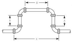
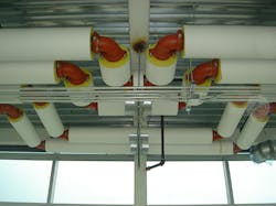
Eight flexible couplings, four grooved-end 90-degree elbows, and three pipe spools are required for each expansion loop. As system temperature falls and the pipe run contracts, the loop expands. Rather than stress the pipe, the movement is absorbed by the couplings at the elbows. As system temperature increases, the opposite occurs: The pipe run expands and the loop contracts, with the couplings accommodating the deflection in the opposite direction. At one-half to one-third the size of a welded loop with the same capacity, grooved expansion loops offer significant space savings (Figure 4 and Photo B).
Building creep. Building creep refers to the shrinkage that occurs over time as construction materials settle. As floors compress, branch piping falls relative to initial installation location. Riser piping, however, remains stationary, creating offsets at branch connections.
A number of methods have been used to handle deflection caused by building creep. In some systems, geometry is employed to connect branch piping to risers, while in others, mechanical couplings or flexible hoses are used. These methods present the same limitations as discussed for settlement.
The grooved method for accommodating building creep is similar to that for accommodating equipment misalignment. If a riser is designed rigidly—with all joints welded or with rigid grooved couplings—the branch connections will need to employ at least two flexible grooved couplings and a length of pipe between them to handle the lateral misalignment resulting from creep. To compute the required horizontal pipe length, divide the anticipated amount of misalignment by the coupling’s deflection-from-centerline capability, taking into account any required design factors.
Accommodating deflection inline with flexible grooved couplings reduces space requirements. The couplings offer a more reliable, maintainable connection than alternative mechanical couplings, and they typically are not subject to the same low-pressure limitations as flex connectors.
Building sway. Riser piping in a tall building often is subject to deflection because of wind loads that cause the building to sway. Freedom of motion should be designed into risers rigidly affixed to a structure to permit them to move in unison with the structure.
Building sway does not always require a specific accommodation methodology. Rigid piping of the lengths seen in buildings subject to measurable sway usually can handle such bend loads. For buildings of certain geometries in particularly windy areas, however, additional accommodation measures, such as mechanical couplings, may be used.
Although the amplitude of sway is much smaller than that of other forms of deflection, specifying a method that accommodates sway along with other forms of movement can reduce pipe-system stress. Deflection because of sway occurs much more frequently than other forms of deflection, so there may be a risk of piping fatigue from cycling.
Flexible grooved couplings have been used successfully on riser piping to allow the piping to sway harmlessly with buildings. Similar to the method for accommodating curvature, the grooved method for accommodating sway entails the use of flexible couplings on riser piping as often as needed.
Summary
Engineers for some of the world’s tallest buildings have used grooved mechanical piping systems to meet their deflection needs. With a decades-long track record, grooved piping can be specified to handle deflection while producing benefits such as design flexibility, a smaller footprint, and reduced system stress, resulting in more durable, reliable, and maintainable systems.
A product engineer specializing in the HVAC and power markets for Victaulic Co., manufacturer of mechanical pipe-joining and fire-protection systems, Gary Hillier is part of a team that provides technical applications assistance and training for the Victaulic product line. He is a member of the American Society of Mechanical Engineers and the National Fire Protection Association and holds a bachelor-of-science-in-mechanical-engineering degree from the University of Central Florida.
Did you find this article useful? Send comments and suggestions to Executive Editor Scott Arnold at [email protected].
