Many system-design ideas that have been proved in commercial buildings, such as parallel pumping, can be applied to industrial facilities. Parallel constant- or variable-speed pumps can increase reliability and reduce operating costs in industrial hydronic pumping systems. Parallel pumping is not a new concept and should not be used, for example, in industrial systems in which redundancy is not important or the opportunity for single-pump operation is limited. However, parallel pumping can offer significant benefits in many other industrial hydronic systems.
HOW DOES PARALLEL PUMPING WORK?
Parallel pumping refers to two or more pumps that are installed with the same suction and discharge headers. The pumps must be selected to provide system design flow and head at the discharge header (Figure 1, Point A). Parallel pumps are beneficial because they:
-
Provide more redundancy and flexibility than a single larger pump at a reasonable cost.
-
Take up less space. Parallel inline pumps may cost even less because they do not require foundations or accessories, such as suction diffusers.
-
Use less energy in variable-volume systems.
-
Provide better than 50-percent flow redundancy during single-pump operation.
Small systems and systems that rarely change flow may not be good candidates for parallel pumps. If required, a designer must be able to provide full system head and flow in spite of a pump failure.
WHY SPECIFY PARALLEL PUMPS?
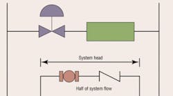
The simplest parallel-pump installations use two small equally sized pumps each selected to provide full system head from Point B to Point A (Figure 1), but only half of full system flow. When both pumps are operating, the system experiences the combined effect of both pumps.
In Figure 2, flow at several head values is identified to plot a single-pump curve; flow then is doubled to plot a parallel-operation curve. Curve S1 represents a friction-only system, while Curve S2 represents a system that has fixed and variable head losses. For these two systems, both pumps must be in operation during full-load hours. A procedure similar to the one used in Figure 2 can be utilized for any number of equally sized parallel pumps. Pumps must be selected to satisfy a system design point, which then can be used to draw a system curve. As system control valves close to decrease flow during part-load hours, the system curve warps to the left, reducing horsepower draw.
A part-load situation can be detected easily and automatically by any of a variety of sensors. Based on sensor input, a parallel-pump controller could destage one of the pumps. The combined-effect parallel-pump curve then would disappear, and the remaining pump would operate at the intersection of its curve and the part-load system curve. As demand increased, the single pump would advance on its curve, increasing horsepower draw. The control system would prevent pump operation at or beyond the end of its curve, turning on the idle pump and causing the original pump to retreat on its curve. Flow once again would be shared between the two pumps. At full-demand conditions, either pump could supply more than 50 percent of design flow, depending on the shape of the system curve.
DESIGN CONSIDERATIONS
In any parallel-pump installation, check valves are crucial, preventing the backward flow that certainly would exist during single-pump operation. Reverse flow through an idle pump costs money and imposes a great deal of torsional stress on the pump shaft as the pump motor stops and then accelerates the shaft in the proper direction. Without check valves, motor damage is likely, even if the shaft can resist the stress, because the motor will draw high currents and develop more heat. A three-in-one valve that combines check, balance, and shutoff functions often is used for this purpose.
Even though each pump is selected for less than full flow, its piping and motor must be sized for the increased flow that occurs during single-pump operation. Therefore, drawing pump and system curves is important because they can predict worst-case flow and horsepower. As previously noted, a pump controller must prevent a pump from operating at the end of its curve by staging on another pump as system flow increases. Therefore, motor selection can be based on the chosen staging point.
REDUNDANCY
Industrial facilities sometimes use two pumps in parallel even though one pump could handle 100-percent head and flow. Two 50-percent pumps can meet design conditions by operating together, and one of the pumps potentially could provide more than 50 percent of the flow. However, if either of the pumps fails, full flow cannot be provided. Any of three 50-percent pumps in parallel can provide a significant fraction of design flow. Any two of these pumps can meet 100 percent of the flow, which allows one pump to be out of commission. Initial costs for improved redundancy can be surprisingly low. Two 50-percent pumps cost only 79 percent as much as two 100-percent pumps, while three 50-percent pumps cost only 18 percent more.
VARIABLE-SPEED PUMPING
The ability to vary motor revolutions per minute gives designers another important energy-saving tool, but it does not necessarily eliminate constant-speed parallel pumps as a design alternative.
In a variable-speed system, a variable-speed-pump controller replaces a parallel-pump controller. A variable-speed-pump controller stages and destages pumps according to load profile, but also varies pump speeds to satisfy a differential-pressure set point in the system, such as the minimum-control head in Figure 2. A high value of minimum-control head makes variable speed less attractive, so it should be minimized by careful sensor placement. The control curve in Figure 2 represents the sum of friction head loss and minimum control head to be maintained by the control system at any amount of flow. The minimum control head in Figure 2 is the differential head maintained by the control system across a selected coil and control valve. In industrial HVAC systems, it is a good idea to install the differential-pressure sensor at a coil located far from the pump so the minimum control head is a small fraction of the total head required. However, as long as flow changes, constant-speed pumps still present an opportunity to save energy and avoid the cost of variable-speed drives, sensors, and controllers.
COMPUTER-BASED SELECTION PROGRAMS
Software programs that make parallel-pump selection quick and easy are available. If the type of system required (heating or cooling, building type, etc.) is known, a load-profile library can be used to estimate the energy-cost savings of parallel- and single-pump operation. The software programs can help avoid pump selections that would cause the single-pump curve to fail to intersect the system curve, resulting in unsatisfactory single-pump operation.
CONSTANT- AND VARIABLE-SPEED PUMPS IN PARALLEL
Often, the objective in using parallel constant- and variable-speed pumps is to minimize a system's initial and operating costs. For example, let's assume that two pumps in parallel each have been selected for full system head and half of full system flow. The system also requires a controller and sensor to provide automatic operation, but initial costs are reduced because only one variable-speed drive is needed and the constant-speed pump requires only a standard motor starter. In a variable-volume hydronic system, the variable-speed pump handles part-load flows up to its full revolutions-per-minute capability and the constant-speed pump is turned off. If flow increases, the constant-speed pump stages on, and the variable-speed pump slows to meet the actual flow requirement. As flow continues to increase, the variable-speed pump again speeds up to the full revolutions-per-minute capacity so that at design flow both pumps are operating at full speed, splitting the flow between them.
A problem arises when a variable-speed pump is making up the difference between a constant-speed pump's capability and required system flow. Point A in Figure 3 represents a requirement for 4,000 gpm at 80 ft of head in a system designed for 4,500 gpm at 100 ft of head. The variable-speed pump cannot meet that point by itself, even running at full speed, so the control system must turn on the constant-speed pump at full speed.
The two pumps then operate at Point B in Figure 3, providing more flow than necessary. The variable-speed pump can be ordered to slow from the full revolutions-per-minute capacity to 1,550 rpm to meet the current flow requirement. At 80 ft of head, the constant-speed pump provides only 2,900 gpm, so the variable-speed pump must make up the difference (1,100 gpm). The variable-speed pump could provide 1,100 gpm by rotating at 900 rpm, but it would develop only 25 ft of head at that speed. Unless the control system maintains a speed of 1,550 rpm, the variable-speed pump will be deadheaded and its check valve will be held closed by the 80 ft of discharge pressure from the constant-speed pump. At 900 rpm, the variable-speed pump would contribute nothing to the system flow and eventually overheat.
The 1,100 gpm provided by the variable-speed pump rotating at 1,550 rpm is an artificially low flow compared with the head developed in the pump volute. It is likely that large, unbalanced pressures will exist in the pump volute, causing excessive loads on the pump shaft and bearings. The shaft and bearings are not fragile; they can withstand excessive loads for some period, but will start to fail as the loads get higher for longer durations.
PRESSURE-BOOSTER SYSTEMS
A variable-speed pressure-booster pump is controlled best by sensing a single point of pressure, preferably near the top of a plumbing system. Compared with an HVAC system, the minimum control head of a plumbing system is greater. Therefore, its control curve is flatter and the range of revolutions-per-minute variation in the variable-speed pump is smaller. A variable-speed pump in a plumbing system cannot slow as much as an HVAC pump. For these reasons, constant- and variable-speed pumps sometimes are operated in parallel by a suitable control system.
DOES CONSTANT-/VARIABLE-SPEED PUMPING MAKE SENSE?
In the early days of variable-speed pumping, adjustable-frequency drives were costly, so using a combination of constant- and variable-speed pumps made sense. Now, an adjustable-frequency drive and a large motor starter cost nearly the same amount, and the primary reason for using constant- and variable-speed pumps in parallel largely has disappeared. In addition, running both pumps at the same variable speed reduces pump-bearing wear and provides energy savings at a cost comparable to the constant-/variable-speed combination. Parallel pumping can offer significant benefits and should be considered for industrial HVAC systems when appropriate.
An HVAC training consultant, Roy Ahlgren is a columnist for Plumbing Systems & Design, a publication of the American Society of Plumbing Engineers. A retired director of ITT Corp.'s Little Red Schoolhouse, he is a member of the American Society of Heating, Refrigerating and Air-Conditioning Engineers and a past chair of its hydronics technical committee.
