Many vibration problems are a result of interactions among a system's pump, motor, fluid, piping, and structure. This interactive relationship requires a systems approach to vibration analysis, rather than the investigation of individual components. Neglecting important factors during pump installation can lead to vibration issues that are expensive and time-consuming to resolve. All pump installations must adhere to manufacturers' recommendations for system-vibration problems to be avoided. However, if a vibration problem occurs, all field and vibration data must be analyzed to determine the cause. Once identified, the correct, most cost-effective solution can be applied to eliminate or minimize the vibration.
WHAT IS VIBRATION?
Vibration is defined as mechanical oscillations or the repetitive motion of an object about an equilibrium point. Simply stated, any object that moves back and forth is vibrating. Examples of vibration include a clock's pendulum in motion, a guitar string that has been plucked, or a tuning fork that has been struck. These examples use oscillation—or vibration—to obtain a desired result. However, vibration in a centrifugal pump can be undesirable and lead to component failure.
Vibration is an indication of a pump's condition. All pumps vibrate at some level of intensity throughout their life cycle. A vibration analysis can help identify normal vibrations that may not be harmful as well as vibrations that exceed acceptable levels and can shorten a pump's life. Because an analysis also may determine the source or cause of a vibration, it can be used as a tool for troubleshooting and preventive maintenance.
WHAT CAUSES VIBRATION?
Able to originate internally or externally, an excitation force is the only cause of vibration. Repeating forces create the vibration problems most commonly associated with centrifugal pumps. These forces often are caused by the rotation of imbalanced, misaligned, or worn pump components.
HOW IS VIBRATION MEASURED?
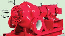
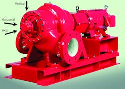
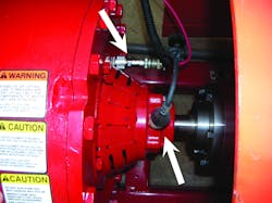
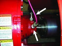
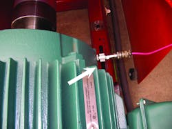
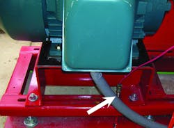
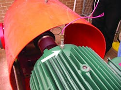
Vibration measurements should be taken at the inboard and outboard bearings of a pump and motor in axial, horizontal, and vertical directions. If a more intensive analysis is required, measurements also should be taken at several places on the pump base. Electronic probes or sensors can be attached at each of these locations, sending electronic signals to a vibration analyzer. Measurements should be taken at operating speed for constant-speed motors and at varying speeds for pumps operating on variable-speed drives.
HOW IS VIBRATION DESCRIBED?
Vibration analyzers convert complex mechanical movements into equivalent electrical signals that can be filtered and measured using efficient algorithms. The resulting spectrum can describe each vibration by frequency, amplitude, and/or phase and used to identify the root cause of a pump's vibration. Confirmation of a vibration source is critical to any major corrective action based on a spectrum.
Frequency describes the oscillation rate of vibration or the speed at which an object vibrates. It is a measure of the number of complete cycles that occur in a specified period of time, such as cycles per second (cps) — also measured in hertz (Hz) — or cycles per minute (cpm). Using cpm to describe vibration frequency allows it to correlate to the rotational speed of the pump, which typically is expressed in revolutions per minute (rpm). If pump speed is 1,800 rpm, and vibration frequency is 1,800 cpm, frequency can be expressed as:
1 × rpm
If pump speed is 1,800 rpm and vibration frequency is 3,600 cpm, frequency can be expressed as:
2 × rpm
The rotational frequency of a pump typically is referred to as the system's fundamental frequency. Many vibrations simply are a multiple of fundamental frequency.
Amplitude. Amplitude describes the severity of a vibration and can be measured and expressed as:
- Displacement, the total distance traveled by a specific component during one complete cycle. It measures the magnitude of the oscillation and can cause stress damage to components. Displacement amplitudes are used at very low vibration frequencies, typically below 600 cpm (10 Hz). High displacement amplitudes at low frequencies can cause a considerable amount of stress damage to a pump. Mounting bolts can snap; concrete bases, foundations, and grout can crack; and base welds can fail.
- Velocity, the maximum speed of a component during a complete cycle. Velocity amplitude gives the most useful information regarding a pump's condition. It is a direct indicator of fatigue because it factors in displacement and frequency. Velocity amplitude measures how often displacement is applied. After a period of time, the component simply wears out because of repeated oscillation. Fatigue failures typically occur at vibration frequencies between 300 cpm (5 Hz) and 120,000 cpm (2,000 Hz). Therefore, if frequencies are within this range, velocity-amplitude measurements are recommended. Fatigue failures occur with pump and motor shafts, couplings, bearings, and bases.
- Acceleration, the force(s) causing oscillation. It shows how quickly velocity changes from one extreme point to the next. Acceleration amplitudes are used when vibration frequencies are above 120,000 cpm (2,000 Hz). Large forces can occur at high frequencies even though velocity and displacement amplitudes are small. Excessive acceleration amplitudes can deform the surfaces of ball bearings and races to the point of failure. Large forces can break down the lubricating film in bearings, also resulting in failure.
Phase. Phase establishes the position of a component oscillating at a given instant with reference to a fixed point or another vibrating component. Simply put, phase lets us compare the relative direction of movement of a specific component. Phase is important because it determines how vibrations interact — whether they are acting with or against each other. If two vibrations occur at the same frequency in a synchronized manner, they are “in phase.” If vibration frequencies are not synchronized, they are “out of phase.” Vibration analyzers and data-collecting equipment typically use a strobe light or digital input to display the phase of a vibration. Determining the relative motion of pump components reduces the number of vibration causes and helps pinpoint problems.
VIBRATION LIMITATIONS
The Hydraulic Institute (HI) publishes recommended vibration limits for a variety of centrifugal pumps. Limits are based on the pump type, mounting configuration, fluid, and horsepower required. Values for each style of pump are described using velocity amplitudes and should be used as general benchmarks. Field vibration amplitudes at or below these limits will not affect a pump's life or reliability. Vibration amplitudes above HI recommendations should be investigated to determine the vibration's cause or monitored for changes. Exceeding maximum limits may be acceptable if the amplitudes do not increase over time and there is no sign of component damage or increased noise levels.
HI's recommendations are based on several critical assumptions. First, a pump must be operating under steady-state conditions at its rated speed with no cavitation or air entrainment. A straight, uniform flow of fluid into the pump is required. Piping should be anchored adequately to avoid any strain on pump flanges. Couplings and components must be aligned to the manufacturer's specifications. Finally, the foundation must have adequate mass and rigidity, and the pump base should be properly leveled, anchored, and grouted (if required).
Pump installations that fail to meet these assumptions may exhibit vibration problems immediately at startup or after many hours of operation. HI assumptions are addressed in most pump manufacturers' installation manuals and should be followed during installation.
HI recommends limits on pump-rotor residual imbalance. International Organization for Standardization (ISO) balance-quality grade (G) 6.3 is used for rotating components to ensure imbalance is kept to a minimum. Impellers, couplers, and rotating assemblies often are balanced to G6.3 to achieve optimal balance based on rpm. G6.3 allows a certain displacement from centerline vs. rpm. At 1,800 rpm, the allowable residual imbalance is 1.2 times 10-3 in. per unit of rotor mass. If increased to 3,600 rpm, the acceptable residual imbalance decreases to 0.7 times 10-3 in. per unit of rotor mass.
Impellers typically are balanced to G6.3 standards after they are trimmed to the correct diameter. If trimmed in the field, the impeller should be balanced again to meet G6.3 standards. Failure to rebalance an impeller could cause a vibration issue.
CAUSES OF VIBRATION
Typical 1-times-rpm vibrations include imbalance, a soft foot, and a bent shaft. Mechanical looseness, misalignment, and resonance can generate vibrations at frequencies of two, three, or more multiples of rpm. Failing bearings typically produce non-integer multiples of pump speed. Hydraulic oscillations show frequencies that are a product of the number of impeller vanes multiplied by rpm.
Vibration frequencies are used to help locate the root cause of a pump's excessive vibration. Knowing the vibration frequency — the first step in the analysis process — can help narrow the possible causes of vibration.
Misalignment. Misalignment is the No. 1 contributor to vibration problems. This occurs when rotating centerlines of two shafts are offset and/or at an angle. Thus, proper coupling alignment is key to avoiding vibration problems. Shaft alignment should occur several times during a pump installation. Initial alignment should be completed prior to the piping of a pump. After piping is complete and the pump base is anchored (but not grouted), the shafts should be aligned again. The final shaft alignment always should be performed under actual operating temperatures. This allows for the contraction or expansion of all system components and ensures proper alignment under actual operating conditions. Alignment should be checked periodically and corrected if needed. Running a misaligned pump can cause extreme heat in couplings and bearings, bent shafts, and increased operating costs. To reduce angular misalignment, consider dial indicators or laser alignment equipment.
Coupling manufacturers publish alignment tolerances that should be followed if not addressed in a pump's installation manual. Different couplings will produce different vibrations, which are characteristics of design and construction materials.
Soft foot. Vibration also can be caused when the feet on a motor frame or pump casing are not on the same plane. Tightening the nut and bolt on a soft foot can distort the base, casing, and/or motor frame, leading to vibration. This is similar to pipe strain on suction and discharge flanges, which can induce a soft foot. Pump and motor shafts can be aligned perfectly and still exhibit excessive vibration because of the distorted frame caused by a soft foot.
To check for soft foot on a motor frame or pump casing, loosen the mounting bolt for each foot individually, checking the vibration level after each change. If a soft foot has occurred, the vibration level will decrease as a mounting bolt is loosened. Shims can be added under a soft foot to correct the condition. Alignment between shafts should be checked after shims are added.
Imbalance. Imbalance is caused when an object's center of mass is different from its center of rotation. As the leading cause of pump imbalance, impellers should meet G6.3 for allowable residual imbalance. For high-rpm pumps, rotating assemblies, including couplings, should be balanced as a unit to meet G6.3. It is reasonable to assume an impeller is balanced at startup, but after operation, an imbalance may be caused by wear. Impeller imbalance also is a frequent cause of mechanical-seal and bearing failure.
Another area of concern for imbalance is the shaft key used for a coupling and impeller. Using the wrong key could adversely affect rotating-assembly balance.
Mechanical looseness. Mechanical looseness should never be overlooked in the field. All mounting bolts, including base-plate, pump, motor, coupler, and guard bolts, can become loose over time. Pipe restraints also should be checked for looseness. Vibration can result from cracked foundations, insufficient contact between grout and pump bases, or cracked grout in base plates. When these problems occur, a pump, base, and foundation no longer are one solid unit. They become several individual units, each with its own natural frequency. It is important to use high-quality non-shrinking grout when installing a base designed for grouting.
Base installation. Poor base installation is another leading contributor to vibration. Foundation bolts of the proper size and number should be embedded in concrete prior to the installation of a pump base. The base should be supported and leveled by properly sized shims at a minimum of each anchor bolt. Nuts should be set to the correct torque based on their size. Any exceptions or modifications to the pump-base installation can lead to vibration issues.
Resonance. Every system has many resonant frequencies. If a system encounters vibrations at these frequencies, amplification will result in premature component failure and increased downtime. Resonance can be avoided by changing a system's frequency, which is determined by the mass, stiffness, and damping properties of all of the components involved, including the pump, base, motor, piping, coupling, guard, foundation, etc. If the resonance vibration is just below the system's natural frequency, the stiffness of the system should be increased so the vibration frequency shifts above the natural frequency. If the resonance vibration is just above the natural frequency, the system's mass should be increased, shifting the vibration frequency below the natural frequency.
Another solution to resonance vibration is to change the operating speed. When a centrifugal pump is operating on a variable-frequency drive, changing the speed in lieu of the resonant frequency can be the most economical option. Drives often are programmed to skip a frequency or two to avoid resonance vibration. This should not be a problem in an HVAC application. Another option is to determine which component in the system is being excited at resonance, then replace the component or modify its resonance frequency.
Cavitation. Cavitation also can cause pump vibration. It occurs when the system's available net-positive suction head (NPSHa) is less than the pump's requirement (NPSHr). Indications of a cavitating pump can include noise, fluctuating flow rates, a decrease in discharge pressure, and vibration. Cavitation-induced vibration is caused by imploding vapor bubbles that introduce shock waves in a pump, shortening the life cycle of all of the pump's mechanical components. The components that commonly fail prematurely are impellers, wear rings, and casings. If cavitation is present, NPSHa should be increased above NPSHr by making changes in the system design or operation to reduce or eliminate cavitation. Cavitation does not always produce pump vibration, and the induced vibration often is random and unmeasurable.
Motors. Finally, motors can be the root cause of vibration. Like centrifugal pumps, motors are built to vibration specifications. Guidelines are given by the National Electrical Manufacturers Association. Unfiltered velocity amplitudes should not exceed 0.12 in. per second zero to peak at bearings for 1,200-, 1,800-, and 3,600-rpm motors. These guidelines are for rigidly mounted uncoupled motors running at no load.
Electrically induced vibration results from unbalanced voltage, broken rotor bars, and air-gap distortion and can be checked by de-energizing a motor while in operation. If the vibration disappears after the motor is de-energized, the vibration is induced electrically. A broken rotor bar prevents current flow, resulting in a lack of a magnetic field. Because the magnetic field causes the rotor's rotation, its absence in one area results in an imbalance force. Air-gap distortion results when the space or gap between the rotor and stator is not perfectly even all of the way around. The strength of the magnetic field is proportional to the gap. Thus, the magnetic field is stronger where the gap is small and weaker where the gap is large. This variation in the magnetic field around the rotor also can produce an imbalance. By understanding vibration, its causes can be identified and corrected.
A senior product specialist in the commercial HVAC pump group for ITT Residential & Commercial Water, Stan Kutin has experience with HVAC-system design, applications, and centrifugal pumps.
