To meet increasingly rigorous mechanical codes and standards, today's ventilation systems must become more sophisticated. Sensible-cooling loads are being reduced as codes require tighter, more energy-efficient building construction, higher-efficiency HVAC equipment, and more precise ventilation. Consequently, latent loads are becoming more significant in overall HVAC load calculations, and, in many instances, design-load sensible-heat ratio (SHR) is below 0.60.
This article discusses the use of heat pipes in outside-air-conditioning designs for new buildings conforming to ANSI/ASHRAE Standard 62.1-2010, Ventilation for Acceptable Indoor Air Quality, and ANSI/ASHRAE Standard 90.1-2010, Energy Standard for Buildings Except Low-Rise Residential Buildings, as a means to improve HVAC performance, indoor-air quality (IAQ), and energy efficiency, as well as for retrofits.
HVAC design for commercial buildings must address effective ventilation with fresh air as required by ASHRAE Standard 62.1 where the most recent version of the standard is incorporated in codes and where Leadership in Energy and Environmental Design (LEED) certification is sought. ASHRAE Standard 90.1-2010 generally does not allow cooling and reheating of the same air stream, but it allows for reheating with recovered energy. One-hundred-percent-outside-air systems have been used for years in specialty buildings such as laboratories and clinics. Designers now are using these dedicated outside-air systems (DOAS) for buildings such as schools and offices as a cost-effective and energy-efficient approach to meeting the requirements of Standard 62.1-2010.
Background
The concept of heat transfer through the capillary movement of a working fluid was patented in 1942. Early in the U.S. space program, NASA employed heat pipes as a means of dealing with heating from the sun-exposed side of a non-rotating spacecraft that threatened failure of heat-sensitive electronics. Other heat-pipe applications include dissipating heat from oil being transported in the Trans-Alaskan Pipeline to avoid thawing the permafrost foundation supporting the pipeline, the cooling of computer central-processing units, and evacuated-tube solar collectors.
The basic heat pipe is a passive refrigeration system that transfers thermal energy from one end of the pipe to the opposite end (Figure 1).
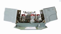
Photo A shows how a heat pipe is wrapped around an air-conditioning cooling coil, allowing air to first go through the portion of the heat pipe upstream of the cooling coil (the precool section), then through the cooling coil, and finally through the downstream portion of the heat pipe (the reheat section). Entering-air temperature is reduced by 5°F to 20°F by the precool section, allowing the evaporator coil to condense more water vapor because of the lower entering wet-bulb temperature. The reheat section of the heat pipe then raises the cooling-coil exit temperature by at least the same 5°F to 20°F. The degrees of precool and reheat depend on the entering-air conditions, the cooling-coil temperature, and coil depth, face area, and fins per inch. When added to a conventional direct-expansion or chilled-water cooling system, a wrap-around heat pipe can significantly increase dehumidification, with the additional energy usage being the fan energy needed to force air through the precool and reheat sections.
Dedicated Outside-Air Systems
Outside-air requirements now specify ventilation effectiveness at the occupant level, as well as airflow at the system level. Conventional mixed-air variable-air-volume systems sometimes are proving inadequate for humidity control while effectively ventilating with verifiable outside-air quantities. A particularly successful design approach is to treat and distribute outside ventilation air with separate equipment and ductwork: a DOAS. A DOAS is designed to satisfy 100 percent of the outside-air ventilation requirements established by ASHRAE Standard 62.1 using a separate cooling/heating/filtration/distribution system. Supply air from a DOAS can be introduced directly into the conditioned space to mix with air from the recirculating HVAC system or can be ducted to mix with recirculating air and the mixed air discharged into the space. Use of a DOAS can allow the design of a smaller, simpler recirculating HVAC system.
DOAS designs can provide the following operating characteristics:
-
Capacity to modulate the dew point of the conditioned outside air so the entire building latent load (ventilation-air latent load plus internal latent loads) is satisfied by the DOAS. A recirculating HVAC system handles only the remaining building sensible-cooling load.
-
DOAS discharge air can be at or lower than space set-point temperature. During most of the cooling season, the dew point of the DOAS discharge will be lower than the dew point of supply air from the sensible-load HVAC system.
DOAS discharge air that is below the space set-point temperature may require heating to avoid overcooling or diffuser condensation problems. To tackle this low-load condition, designers are applying the concept of neutral air, where DOAS supply temperature is the same as space temperature (space neutral), while the DOAS discharge dew point is low enough to control relative humidity when ventilation air is introduced and mixed in the conditioned space.1
Figure 2 is an example of a DOAS unit with heat pipes supplying near-neutral air to a space to be maintained at 75°F and 50 percent RH. The design air state points on the psychrometric chart are matched to the schematic of the DOAS and the recirculating air-conditioning units, and the design values for conditioned air are:
-
Outside air is 85°F DB, 72°F WB.
-
DOAS conditions outside air and supplies it at 69°F DB, 50°F DP.
-
The recirculating units take air from the conditioned space at 75°F DB, 55°F DP (62.7°F WB) and supply it at 69°F DB, 60°F WB (55°F DP).
The design dew-point temperature of DOAS supply air would be further reduced to meet internal moisture loads from occupants, activities, and processes, as needed. The recirculating-system supply-air temperature would be lowered or raised to meet the sensible-cooling or heating load, as needed.
Dehumidification
In many climate zones, annual outside air dehumidification needs are two to 10 times the annual sensible loads.2 Treating ventilation air cannot be efficiently accomplished by conventional HVAC systems that operate at a 0.65 to 0.80 SHR; that is, 65 percent to 80 percent of their capacity provides temperature reduction, leaving only 20 percent to 35 percent remaining for dehumidification. Cooling coils alone could be increased in size to condense adequate water vapor to handle latent loads, but the resulting discharge temperatures are too low for introduction into the conditioned space and energy-intensive reheat is required (Figure 3).
In the example shown in Figure 4, a heat-pipe assembly is added to the cooling coil, providing a precool section that sensibly cools outside air by 17°F and uses two coils to remove much more water than the cooling coil alone. On the exit side of the cooling coil, the reheat section raises the temperature by 17°F. Together with 2°F motor reheat from the supply fan, this DOAS achieves neutral air at 75°F.
As outside-air temperature drops, the temperature of the heat-pipe reheat section also drops. Wrap-around heat pipe coils can be selected for design conditions, and they will tend to self-modulate to provide more consistent DOAS discharge temperature and relative humidity than a cooling coil alone.
Life-Cycle Cost Comparison
To perform a life-cycle-cost analysis of technologies providing the dehumidification capability required in a DOAS, the following are evaluated over the life of the equipment:
-
Capital cost for factory-installed and site-installed applications.
-
Additional parasitic fan energy costs.
-
Cooling costs from the chilled-water system or direct-expansion compressor.
-
Reheat energy costs.
-
Maintenance and replacement costs over the expected life.
The following example compares wrap-around heat pipes with a pump-around heat-exchanger system using glycol/water as the working fluid. They both have precool and reheat heat exchangers installed before and after the cooling coil, respectively.
DOAS Design Example
Consider a DOAS application for a new building being designed to U.S. General Services Administration (GSA) standards. When using a DOAS, GSA requires that the system maintain conditioned-space air at a dew point of 55°F or less and supply air at no lower than 50°F dew point and 52°F dry bulb.3 The following design details are used in the comparative analysis. The psychrometric state points for the heat pipes and the pump-around system are the same.
-
DOAS supplies 5,000 cfm of outside air conditioned to a neutral-air state of 75°F DB, 50 percent RH, 55°F DP, 62.5°F WB, 65 grains per pound.
-
Design outside-air conditions are 95°F DB, 78°F WB, 47 percent RH, 71.8°F DP, 117 grains per pound.
-
Reheat-coil discharge air is at 73.2°F DB and 61.9°F WB, with 1.8°F of motor reheat to give supply air at room conditions: 75°F DB, 62.5 WB, 50 percent RH, 55°F DP, 64.9 grains per pound.
-
Configuration per side for the pump-around system is six rows of tubes with 11 fins per inch. For heat pipes it is four rows with 10 fins per inch. Heat-pipe heat exchangers are smaller than glycol/water exchangers becuase of better heat transfer.
Energy Costs
With the same supply fan for both applications, the additional fan energy needed to move air through the added coils is calculated from the coil pressure loss: pump-around system, 0.44 in. w.c. (per side); heat-pipe system: 0.28 in. w.c. (per side).
In addition, the pumping friction loss for recirculating glycol/water though the coils in the pump-around system amounts to 10.3 ft of head per side. The heat pipes are passive, requiring no significant energy to circulate the working fluid (refrigerant). The power requirements for the two systems are: pump-around system, 1.28 bhp (fan and pump); heat-pipe system: 0.73 bhp (fan only).
Both systems operate for 3,000 hr per year; the fan/motor combination is assumed to be 54 percent efficient, and the pump/motor combination is 72 percent efficient (motors are 90 percent efficient). Electricity costs are $0.095 per kilowatt hour and a monthly demand charge of $7.45 per kilowatt is used in the calculation, resulting in annual energy costs of $397 for the pump-around system and $228 for the heat pipe system.
Life-Cycle Costs
The installed capital cost is assumed to be $5,700 for the glycol/water pump-around system and $7,000 for the heat-pipe system. The only additional cost assumed for comparing the two systems is annual maintenance, as both have a nominal 15-year lifetime. The pump-around system is assumed to need maintenance of pumps and valves, as well as labor to clean the coils, fix leaks, and monitor the glycol/water solution. This annual maintenance cost is assumed to be $310. Heat-pipe system maintenance is assumed to be $100 for annual coil cleaning and occasional solenoid-valve parts replacement.
To evaluate life-cycle costs of both systems, the U.S. Department of Energy's Building Life Cycle Cost modeling software, BLCC 5, was used.4 The project was assumed to be located in Georgia and the life of both systems was assumed to be 15 years, with a 1 percent salvage value. Using the assumptions listed in Table 2, the life-cycle cost of the pump-around system is $14,763; for the heat-pipe system it is $11,075.
This analysis indicates the life-cycle cost of the heat-pipe system is 24 percent less than that of a comparable glycol/water pump-around system. The payback period from energy savings alone is 7.7 years; when maintenance savings are considered, it is 3.4 years.
Conclusion
Heat-pipe modules around cooling coils offer designers a reliable, energy-efficient and low-maintenance system for meeting building latent loads and providing good IAQ. With even relatively small DOAS applications, heat pipes are more cost-effective than pump-around glycol/water systems, and the life-cycle-cost advantage grows with the scale of the DOAS.
References
-
Brooke, T. (April 2007). Neutral air units with heat pipes in chilled water systems. Available at: http://www.heatpipe.com/HomePage/mktg_materials/mktg_mats.html
-
Harriman, L., Plager, D., & Kosar, D. (1977, November). Dehumidification and cooling loads from ventilation air. ASHRAE Journal, pp. 37-45.
-
U.S. GSA. (2010). Facilities standards for public buildings. U.S. GSA Standard P100. Washington, DC: U.S. General Services Administration.
-
U.S. Department of Energy, Federal Energy Management Program. Building life-cycle cost (BLCC) programs. Available at: http://www1.eere.energy.gov/femp/information/download_blcc.html
Did you find this article useful? Send comments and suggestions to Senior Editor Ron Rajecki at [email protected].
Richard Combes, PE, PhD, has managed numerous commercial-building HVAC-application projects, and currently is working on a U.S. Department of Defense project under the Energy Saving Technology Certification Program to demonstrate new technology for commercial unitary HVAC systems. Michael K. West, PE, PhD, is a principal HVAC systems scientist with Advantek Consulting and a member of HPAC Engineering's Editorial Advisory Board. He is responsible for the development and testing of new HVAC technologies, as well as the engineering of energy-efficiency and indoor-environmental-quality projects throughout the United States and the Caribbean.
