In many large commercial buildings, central-station air handlers are used to maintain occupant comfort. Often, these units include return fans, which draw air from occupied spaces for recirculation or exhaust. Commonly, the return fans are controlled with variable-frequency drives (VFDs), which receive a speed signal based on building differential static pressure—the difference between interior-space static pressure and outside-air static pressure.
Building differential static pressure commonly is measured with a sensor with two ports: a high-pressure port and a low-pressure port. Tubing extends from both ports. Commonly, low-port tubing is extended to the outside of a building, while high-port tubing is extended to an interior space. The sensor determines the difference in static pressure between the two ports, which it can report to a building-automation system. Typically, this is done as part of a strategy to keep interior-space pressure slightly positive relative to outdoor pressure, reducing infiltration that could lead to comfort and/or indoor-air-quality (IAQ) issues.
The recent retro-commissioning of two office buildings—one 25 stories and 500,000 sq ft, the other 24 stories and 200,000 sq ft—served by central-station variable-air-volume air handlers in California revealed substantial opportunities for optimizing pressurization-control systems in large commercial buildings. This article will discuss two such opportunities: outside-air-static-pressure-measurement termination and control sequences.
Outside-air-pressure-tubing termination
In both retro-commissioned buildings, the low port of each pressure sensor was open to the control panel in which the sensor was installed, not extended to the outside via tubing.
In one building, the control panel was in the penthouse mechanical room, which was open to the outside via boiler outside-air-intake louvers. While that location was good for minimizing wind effects and protecting the sensor from rain, readings likely were not representative of true outside-air static pressure because the panel was in a room containing equipment (boiler burner fan, exhaust fans, etc.) that could have a significant effect on the pressure in the space.
In the other building, the control panel containing the sensor was located in the return-air plenum, on the discharge side of the return fan. At this location, with the low-side port open to the panel and, thus, the plenum, the pressure sensed by the low-side port was higher than the pressure sensed by the high-side port. There was intent to extend the tubing to the outside, as evidenced by a hole in the adjacent exterior wall, but the tubing never was installed.
It is worth mentioning that neither of the buildings was commissioned originally.
The termination of low-port tubing is important, as the wind can have a significant impact on measured outside-air pressure. For example, a 10-mph outside breeze translates to wind pressure of 0.05 in., per Bernoulli's Equation. This light breeze can have a significant impact on pressure control, as pressurization systems typically operate to maintain a slightly positive building pressure in the same range (0.05 in.).
Many outside-air-pressure-sensing devices are available for installation at low-port-tubing terminations. Designed to minimize the effects of wind speed, these devices typically consist of two plates, with the sensing element in the middle of the inside surface of one of the plates. Most manufacturers, as well as the American Society of Heating, Refrigerating and Air-Conditioning Engineers (ASHRAE),1 recommend installation of the devices 10 to 15 ft above a building to further minimize wind effects.
Building-Pressurization-Control Scheme
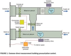
The building-pressurization-control scheme for the two retro-commissioned buildings is similar to the one employed in many buildings with central-station air-handling systems: Return-fan speed is varied to maintain a set differential between interior-space and outside-air pressure. The two buildings also employ an economizer-damper-control scheme that is fairly typical: The economizer-damper controller sends a signal to control outside-, return-, and relief-air dampers, with the return-air dampers operating opposite of the outside- and relief-air dampers (Figure 1).
These control schemes can cause performance issues because the control sequences overlap somewhat: The relief-air damper operates based on the economizer-damper signal (temperature- or enthalpy-based control), but is an integral part of the building-pressurization-control scheme (pressure-based control).
For example, on a past retro-commissioning project, the pressure in the main air handler's mixed-air plenum was positive during the minimum-outside-air operation. (Normally, a mixed-air plenum should be at a negative pressure to draw in outside air.)
Instead of outside air being drawn in, return air was being exhausted through the outside-air damper; in other words, the system was operating in 100% recirculation mode. This issue was attributable to oversized return-air dampers—typically, return-air dampers should be smaller than outside- and relief-air dampers in return-fan systems2—and the overlap of temperature- and pressure control strategies.
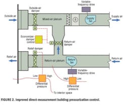
A better method may be to control the relief damper to maintain building differential pressure and control the return fan to maintain return-air-plenum pressure3 (Figure 2).
With this scheme, the relief-air damper is controlled directly by pressure instead of the economizer cycle, and the return fan operates to ensure there is enough pressure in the return-air plenum to push air through either the relief-air damper or the return-air damper. The outside- and return-air dampers would continue to be controlled based on the economizer cycle.1 Note that proper sizing of the outside, return, and relief dampers are required to help ensure sufficient outside-air intake during non-economizer operation.
Converting a control system from the arrangement in Figure 1 to the arrangement in Figure 2 would require minimal capital outlay, as no major system modifications beyond the addition of a pressure sensor and related points and the modification of control sequences would be required. Depending on the as-found performance of a system, such a conversion could result in reduced energy use through return-fan-speed reduction and increased indoor environmental quality through the adequate outside-air intake.
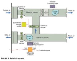
Another possible improvement involves the use of a relief fan instead of a return fan. A relief fan is located downstream of the return-air plenum, drawing air from the plenum and pushing it through the relief-air damper (Figure 3). The relief fan should be controlled to maintain building pressurization, not used as part of an economizer-control scheme.
Typically, it will not need to operate during the minimum-outside-air mode.3 For a relief fan with a VFD, the relief damper is closed when the fan is off and open when the fan is on. In buildings utilizing return fans, changing to a relief-fan system may not be feasible because of space constraints and cost.
In buildings with a relief-fan arrangement already in place, an investigation of system performance is worthwhile; as with a return-fan system, check the low-port-tubing termination and control sequences.
Another method of building-pressurization control is indirect, by which supply- and return-air volumes or intake- and exhaust-air volumes are measured instead of interior/outside pressures. For an existing building with a direct-measurement control system already in place, this may not be feasible because of the space required for the proper installation of airflow-measuring stations.
Common Clues
Following are indicators of a possible issue with a direct-measurement building-pressurization-control system's operation:
- Return or relief fans operate near 100-percent speed most of the time.
- Building differential static pressure fluctuates widely and/or rapidly.
- Return- or relief-fan speed fluctuates widely and/or rapidly.
- Exterior doors are hard to open or do not close securely.
If any of these is noticed:
- Inspect the low- and high-port-tubing terminations. Ensure the high-port tubing terminates at a location representative of the space pressure and away from doors and that the low-port tubing terminates in an accessible location and a manner minimizing wind effects. Consider installing an outside-air-pressure-sensing device at the low-port termination to mitigate wind effects.
- Check and, if necessary, adjust the calibration of the differential pressure sensor.
- Inspect the integrity of the tubing between the sensor and interior and outdoor spaces.
- Review the control sequences. If building differential pressure is controlling the return fan(s), consider using the signal to control the relief-air damper instead and installing a pressure sensor in the return-air plenum to control return-fan speed. The economizer-damper-control sequence would need to be modified as well.
- Ensure the outside-, return-, and relief-air dampers are sized properly.2
- Trace the return-air pathway from the interior space to the fan. Ensure return-air grilles/openings are sufficient and that the pathway is not obstructed by interior walls extending to the floor deck above (for return-air plenums), closed fire/smoke dampers, or damaged internal duct insulation.
For more information on building-pressurization-control systems, including the diagnosis of problems and testing of performance, see “Functional Testing Guide: From the Fundamentals to the Field.”4
Conclusion
Many large commercial buildings utilize direct-measurement building-pressurization-control systems. Optimizing the performance of those systems as part of a retro-commissioning project can yield energy savings and improved IAQ through reduced return/relief-fan speeds, reduced infiltration, and proper outside-air intake.
ASHRAE President Gordon V.R. Holness, PE, ASHRAE, has urged ASHRAE members to focus on increasing energy efficiency in existing buildings.5 Optimizing the performance of building-pressurization systems can be a low-cost method of doing that.
References
- ASHRAE. (2007). 2007 ASHRAE handbook - HVAC applications (ch. 46). Atlanta: American Society of Heating, Refrigerating and Air-Conditioning Engineers.
- Lizardos, E., & Elovitz, K.M. (2000, April). Practical guide: Damper sizing using damper authority. ASHRAE Journal, pp. 37-43.
- Taylor, S.T. (2000, September). Comparing economizer relief systems. ASHRAE Journal, pp. 33-40, 42.
- PECI. (n.d.). Functional testing guide: From the fundamentals to the field. Portland, OR: Portland Energy Conservation Inc. Available at http://www.peci.org/ftguide/ftg/index.htm
- Holness, G.V.R. (2009, August). Sustaining our future by rebuilding our past: Energy efficiency in existing buildings — Our greatest opportunity for a sustainable future. ASHRAE Journal, pp. 16-21.
Dave Moser, PE, is a senior engineer for Portland Energy Conservation Inc. Focusing on commercial-building energy efficiency, he manages the technical aspects of utility retro-commissioning programs, leads in-building retro-commissioning projects, and conducts research. He can be contacted at [email protected].
