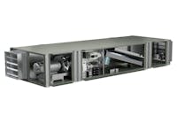
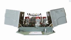
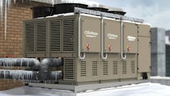
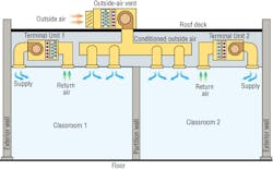
The concept is straightforward: condition and deliver fresh ventilation with a dedicated outdoor-air system (DOAS) to treat outdoor air and space latent loads efficiently. The engineering of dedicated outdoor-air equipment has been well-developed since the turn of the century. Yet, a Web search for “DOAS” still is more likely to point to the classic play “Death of a Salesman” or “differential optical absorption spectroscopy” than “dedicated outdoor air systems.”
This article will explain engineering aspects of two DOAS-related innovations. Both technologies are mature, with more than a decade of successful application, use readily available components, and can be cost-efficient in a well-designed system. Engineers can achieve equal or better performance without the complexities and cost of a reheat coil and controls. Little or no excess cooling capacity and avoidance of reheat translates into significant energy savings. How can designers benefit from DOAS and not end up buried in a costly, complex design?
The advantages of DOAS are compelling. First, with DOAS, the proper amount of fresh air can be sent to each room at all times, rather than rely on ventilation-effectiveness estimates, variable-air-volume- (VAV-) box minimums, and probability to meet ANSI/ASHRAE Standard 62.1-2007, Ventilation for Acceptable Indoor Air Quality. Standard 62.1 requires that every occupied space be served with sufficient outdoor air to meet a space's ventilation requirements under all load conditions. Second, DOAS detach latent from sensible cooling. Therefore, it is a relatively simple matter to provide ample dehumidification without excessive reheat in highly insulated, heat-reflective, cool-roofed buildings. The dehumidification capacity needed to meet Standard 62.1 is calculated at the outdoor design dew point with solar loads at zero.
After ventilation and dehumidification requirements have been fulfilled, terminal units operating in parallel with DOAS need only handle the remaining sensible load. Terminal units could include fan-coil units, radiant-cooling panels, water-source heat pumps, or any other cooling equipment. The terminal units used with DOAS are much smaller and simpler than the types of equipment utilized in systems without DOAS.
DOAS are being installed on a number of projects because of persuasive advantages, so why are we not witnessing the full paradigm shift to large numbers of DOAS that was predicted in 2001?1 In the HVAC industry, change is measured by decades. Even though DOAS have been tested and applied for more than 10 years, they still are deemed “exotic technology” by some mechanical engineers. DOAS also may not be considered on some projects because of perceived higher first and energy costs and specialized controls and components with foreboding names, such as “hot-gas bypass” and “enthalpy recovery wheel.”
Concepts
As its name indicates, a dedicated outdoor-air unit is designed to condition 100-percent outdoor air. Unlike return air from a space, which has a relatively constant temperature and humidity, outdoor air can run wild from a chilly, dry spring morning to the hottest, most humid summer afternoon. An outdoor-air unit must be able to cool and dehumidify a broad range of entering-air conditions to meet design leaving-air conditions. In contrast, the cooling-coil entering-air conditions of a mixed-air unit are buffered by an airflow that is partly outdoor air mixed with mostly return air. The dehumidification demand on an outdoor-air unit is more challenging than that on a mixed-air unit simply because entering-air conditions vary so much.
In a DOAS, the design leaving-air condition of an outdoor-air unit depends on the supply-air dew point needed to meet space latent load. At one extreme—zero space latent load—DOAS supply-air dew point is equal to space-air dew point. In this limiting case, 75°F/50-percent-relative-humidity space air has a 55°F dew point. As occupants are added to a space's design, the amount of outdoor air increases, space latent load increases, and design supply dew point drops.
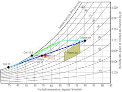
In the classic example of a 690-sq-ft classroom with 35 occupants and 452-cfm ventilation air, the DOAS design leaving dew point is 48.6°F. Continuing with this example, 452 cfm from a DOAS at 48.6°F gives 12,887 Btuh of sensible cooling to a space:
1.08 × 452 cfm × (room temperature - leaving-air temperature)
where:
Room temperature = 75°F
Leaving-air temperature = 48.6°F
1.08 × 452 cfm × (75°F - 48.6°F) = 12,887 Btuh
Now, here comes the problematic element of the design. What if the space sensible load is less than the sensible capacity—12,887 Btuh in this example? In this example, the sensible load on a cool, cloudy day during which the heat loss via the envelope equals the heat gain from lighting and equipment would equal 8,960 Btuh. DOAS supply air of 48.6°F would overcool the space. To avoid overcooling, the DOAS supply air must be heated by 8°F:
(12,887 Btuh - 8,960 Btuh) ÷ (1.08 × 452 cfm) = 8.0°F
Leaving-air temperature = 48.6°F + 8.0°F = 56.6°F
Designer's Dilemma
There are any number of methods of raising the DOAS supply temperature to 56.6°F from the DOAS cooling-coil leaving-air temperature of 48.6°F. One of the most efficient is heat exchange with a building's exhaust air. ANSI/ASHRAE/IESNA Standard 90.1-2007, Energy Standard for Buildings Except Low-Rise Residential Buildings, requires exhaust-air energy recovery on systems larger than those utilizing 5,000 cfm and 70-percent outside air. Unfortunately, many buildings do not have an available exhaust-air stream, either because (1) the exhaust air is not collected into a main duct, or (2) the exhaust amount is insufficient, and relief air is not needed for building pressurization. In these cases, heat-exchange wheels or cubes are not on the designer's menu once heat-exchange effectiveness drops below the 50-percent requirement.
Standard 90.1-2007 prohibits the use of reheat except in very specific cases, and most building energy codes prohibit reheat for good reason: Adding new heat is thermodynamically the same as purposely increasing space sensible load—it is equivalent to running a toaster oven in the previously mentioned classroom example. Recovered reheat also is discouraged because it cancels out cooling. Rather than increasing the sensible load or canceling sensible capacity, runaround methods convert the excess sensible capacity of the DOAS into needed latent capacity. Two types of runaround coils well suited to DOAS are (1) heat-pipe coils for the air stream and (2) heat exchangers for refrigerant flow in direct-expansion (DX) equipment. Converting the excess sensible capacity is a more energy-efficient approach because the equipment delivers all of the cooling capacity it produces.
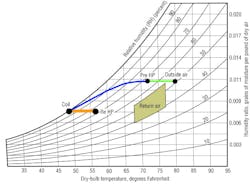
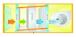
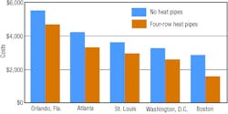
Used in chilled-water and DX systems, heat-pipe coils capture heat from the outdoor-air intake and transfer it downstream of the coil. Patented heat-pipe coils can do this without moving mechanical parts or electric energy input other than a small increase in fan power. Heat-pipe coils can provide the 8.0°F of reheat needed in the previously mentioned example and, at the same time, pre-cool entering outdoor air by 8.0°F. Pre-cooling increases the latent capacity of the cooling coil—as with any coil, the sensible-heat ratio drops with entering wet-bulb temperature—and chilled-water usage is significantly less, saving energy. Using heat-pipe coils, the needed reheat energy is free. Heat-pipe coils used with DX equipment allow smaller compressors, but sometimes are restricted in depth by physical space or fan power.
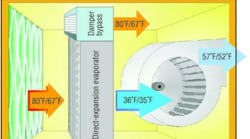
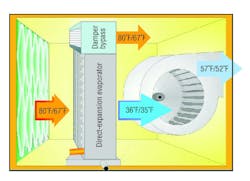
Refrigerant heat exchange offers additional benefits to DX units. Similar to heat pipes, heat is transferred around the cooling coil, except the heat is transported via refrigerant instead of air. In a patented system, a bypass damper is modulated to achieve the needed cooling-coil leaving-air dew point by varying the cubic feet per minute per ton of cooling. A heat exchanger captures heat from the liquid line upstream of the cooling coil and transfers it to the suction line downstream of the cooling coil. At the same time, pre-cooling liquid refrigerant entering the expansion device increases latent capacity and energy efficiency. Very low dew points can be achieved. This uncomplicated low-cost approach is well suited to projects using DX units.
Control
Because runaround methods are passive, they do not add to a system's energy use. However, just like heat-exchange wheels and enthalpy exchangers, their effect tends to vary with entering-air conditions. Manufacturers have developed controls to compensate for this variation.
When the outside-air temperature is 80°F, a heat pipe provides 8°F reheat. When the outside-air temperature is 90°F, a heat pipe would give 10.5°F reheat. Because less reheat generally is needed as the outside-air temperature increases (because the envelope sensible load increases as well), the heat pipe is controlled via refrigerant valves. Valves sequentially close when less reheat is needed and open when more reheat is needed.
Similarly, when the outside-air temperature is 80°F, modulating the bypass damper controls DX coil dehumidification. When the outside-air temperature is 90°F, the damper modulates closed, and more sensible cooling is provided. Generally, rising outside-air temperature usually is coincident with a decrease in outside-air relative humidity. The resulting warmer coil entering wet-bulb temperature usually would mean reduced latent-cooling capacity with the DX coil alone. Controlled dehumidification of the refrigerant runaround system compensates for this loss and provides the design supply-air dew point at nearly all outside-air conditions.
Performance
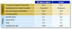
Temperatures and cooling capacities are presented in Table 1 for three DOAS delivering 1,000 cfm outdoor air. The first row, “48°F Coil,” is a benchmark cooling coil presented for comparison. The second row, “DX RaR,” is the DX runaround system. The bottom row is the heat-pipe chilled-water system. All three have been selected to meet the design leaving dew point of 48.6°F for the classroom example; therefore, all three provide essentially equal latent-cooling capacity. Because a cooling coil alone overcools, it requires 8,472 Btuh of reheat. The DX RaR and heat-pipe systems deliver supply air at the desired 56.6°F temperature and 48.6°F dew point and do not require additional reheat energy.
Table 2 compares energy usage of the three 1,000-cfm DOAS systems. Because the cooling coil alone provides excess cooling capacity, it consumes more electrical energy and requires heat energy to cancel out the excess sensible capacity. The benchmark energy efficiency before new reheat is 10.1 Btuh per watt, and total efficiency, including reheat energy, is 6.5 Btuh per watt. The DX RaR and heat-pipe systems deliver just the right amount of sensible and latent cooling to meet the space load, which maximizes energy efficiency at 11.6 and 11.8 Btuh per watt respectively (15-percent and 17-percent improvement in energy efficiency compared with recovered reheat).
Conclusion
Engineers can achieve equal or better performance—without the complexities and cost of a reheat coil and controls—using DOAS equipped with heat-pipe coils and/or using DX DOAS based on refrigerant runaround and coil bypass. Because of their inherent simplicity, they have a lower first cost than comparable units relying on enthalpy wheels and/or hot-gas or liquid reheat coils and controls. Little or no excess cooling capacity and avoidance of reheat translates directly into significant energy savings relative to a cooling coil alone. DOAS like these are similar to the mixed-air units that engineers are comfortable specifying and hopefully will encourage engineers to sustain the long-predicted paradigm shift to DOAS.
References
-
Mumma, S., & Shank, K. (2001). Selecting the supply air conditions for a dedicated outdoor air system working in parallel with distributed sensible cooling terminal equipment. ASHRAE Transactions, 107, 562-571.
-
Brooke, T. (2010, January). Wrap around heat pipes in DOAS units. Paper presented at the ASHRAE Winter Conference, Orlando, FL.
A member of HPAC Engineering's Editorial Advisory Board, Michael West, PhD, PE, is the principal building-systems scientist for Advantek Consulting Inc. He is responsible for the development and testing of new HVAC technologies, as well as the engineering of energy-efficiency and indoor-environmental-quality projects throughout the United States and the Caribbean. A recipient of the Association of Energy Engineers' (AEE's) International Project of the Year award, he has extensive experience applying renewable sources of energy. He is an active member of AEE and the American Society of Heating, Refrigerating and Air-Conditioning Engineers. For patent information on the technologies referenced in this article, contact the author via e-mail at [email protected].
RESOURCES
For additional information on this topic, check out:
Bradley, B., & Stanke, D. Dedicated ventilation systems. (n.d.) Retrived from www.trane.com/commercial/uploads/pdf/673/enews_30_03_090601.pdf
Brooke, T. (2007). Neutral air units with heat pipes in chilled water systems. Gainesville, FL: Heat Pipe Technology Inc.
Mumma, S. DOAS supply air conditions. (2008). Retrived from doas.psu.edu/IAQ_DOAS_SA_Cond_Sp_08.pdf
Murphy, J. (2006, July). Smart dedicated outdoor air systems. ASHRAE Journal, pp. 30-37.
Desert Aire. (2005). 100% outdoor air dehumidification methods. Milwaukee, WI: Desert Aire.


