Reducing the amount of outdoor air entering a space when an HVAC system is mechanically cooling or heating and an air-side economizer is inactive has distinct advantages. For some spaces, demand-controlled ventilation (DCV) based on changes in occupancy may be desirable. According to one method of DCV, ventilation rate is adjusted based on carbon-dioxide (CO2) level. Unfortunately, many designers do not have a clear understanding of the relationship between CO2 and ventilation and the requirements for proper ventilation control. This article will clarify the relationship between CO2 level and ventilation rate and offer suggestions for improving traditional single-setpoint CO2 DCV through the addition of a direct outdoor-airflow-measuring device.
Application of DCV
Generally, DCV should be considered only for high-occupant-density spaces with potential for significant changes in population density. Most standards and rating systems (American Society of Heating, Refrigerating and Air-Conditioning Engineers [ASHRAE]; Title 24, Part 6, of the California Code of Regulations; Leadership in Energy and Environmental Design [LEED]) consider high occupant density to be 25 or more people per 1,000 sq ft. DCV should not be considered for low-occupant-density spaces because the uncertainty of most DCV techniques is too great and the potential benefit too meager for practical application.
CO2 Level and Ventilation
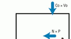
Indoor CO2 level is used to estimate outdoor-airflow rate per person based on a steady-state relationship (Figure 1), which can be applied to single-zone systems.
Mass-balance equation:
(In = Out)
Co × Vo + N × P = Ci × Vo
where:
Co = Outdoor-air CO2 concentration, standard cubic feet per minute of CO2 per cubic feet per minute of air
Vo = Outdoor-airflow rate, standard cubic feet per minute of air
N = CO2-generation rate, standard cubic feet per minute of CO2 per person
P = Number of people
Ci = Inside CO2 concentration, standard cubic feet per minute of CO2 per cubic feet per minute of air
This simplifies to:
N ÷ (Ci − Co) = Vo ÷ P = R
where:
R = Rate, standard cubic feet per minute of air per person
The model's ability to predict source airflow rate per person is dependent on CO2-production rate, which can vary significantly with activity and age. A typical adult produces 0.0084 scfm of CO2 per met; for office work, the activity level of an adult is approximately 1.2.1 Thus, for an average adult with an activity level associated with office work:
R = 0.010080 ÷ (Ci − Co)
Because CO2 sensors report CO2-concentration levels in parts per million, the equation is more useful written as follows:
R = 10,080 ÷ (Ci* − Co*)
where:
Ci* = Inside CO2 concentration, parts per million
Co* = Outdoor-air CO2 concentration, parts per million
With single-zone systems, a 700-ppm rise in indoor CO2 concentration results in an outdoor-airflow rate of approximately 15 cfm per person. This approximates the minimum ventilation rate established to dilute body odor. Also, it relates to historical references (including ASHRAE Standard 62-1989, Ventilation for Acceptable Indoor Air Quality) to a 700-ppm differential as an indicator of acceptable ventilation.
Because outdoor CO2 level typically hovers around 400 ppm, an indoor CO2 level of 1,100 ppm would suggest the body odor generated in a space would be maintained at acceptable levels.
ANSI/ASHRAE Standard 62.1-2010-Compliant CO2-Based DCV
The ventilation-rate procedure in Section 6 of ANSI/ASHRAE Standard 62.1, Ventilation for Acceptable Indoor Air Quality, has not changed significantly since 2003, when breathing-zone outdoor-air requirements (Section 6.2.2.1) were adjusted to include a floor-area component reflecting the dilution needed for building-related contaminant sources. Today, breathing-zone outdoor-airflow rate, Vbz, is calculated based on table values, as follows:
Vbz = Rp × Pz + Ra × Az
where:
Rp = Outdoor-air rate per person
Pz = Number of persons
Ra = Outdoor-air rate per floor area
Az = Floor area
Traditional fixed-CO2-setpoint DCV. As a result of changes to ANSI/ASHRAE Standard 62.1 in 2003, a fixed CO2 setpoint no longer will result in specified ventilation rates, unless the setpoint is calculated at the lowest expected occupancy (i.e., when ventilation rate is highest).
The relationship between space CO2 level and outdoor-airflow rate per person for a 1,000-sq-ft classroom with a variable occupancy of up to 35 students is illustrated in Figure 2.
The relationship between outdoor airflow and the CO2 level required for compliance with ANSI/ASHRAE Standard 62.1-2010 is a variable and illustrated in Figure 3.
A single CO2 setpoint provides required ventilation for a single population. Excessive population results in a ventilation rate greater than that required by ANSI/ASHRAE Standard 62.1-2010, while deficient population results in a ventilation rate less than that required by ANSI/ASHRAE Standard 62.1-2010. Consider, for example, a CO2 setpoint of 1,000 ppm, which equates to a ventilation rate of approximately 17 cfm per person under the assumptions of steady-state, office-level activity and an outdoor CO2 level of 400 ppm. Figure 4 shows the relationship between ventilation and the requirements of ANSI/ASHRAE Standard 62.1-2010 when a 1,000-ppm CO2 setpoint is maintained. Note that this method will overventilate when population exceeds 15 people and underventilate when population falls below 15 people. Additionally, the CO2 response line will rotate around the origin (0,0) if activity level differs from that assumed. Activity-level variations can affect the outdoor-airflow-intake rate of CO2-based DCV systems significantly (typically, resulting in overventilation). The response also will shift if indoor or outdoor CO2 level is inaccurate.
To limit over- and underventilation, most strategies attempt to limit minimum and maximum ventilation rates (Figure 5).
Most designs feature minimum and maximum outdoor-air-intake-damper positions to limit the range of CO2-based DCV. Unfortunately, a fixed damper cannot ensure proper airflow rate is maintained because of:
- Damper-linkage and actuator hysteresis.
- Variable-air-volume-mixed-air-plenum-pressure variations.
- Wind and stack-pressure changes on systems.
These factors can result in outdoor-airflow fluctuations of 50 percent or more in some systems.2
Direct measurement of outdoor air allows systems to limit intake airflow to a desirable range, as depicted in Figure 5. This seemingly small modification of the traditional DCV strategy can improve building performance significantly by eliminating over- and underventilation of outdoor air during periods when a building is operating in minimum-outdoor-air mode.
Overventilation can result in temperature- and humidity-control problems, increased energy use, and decreased system life. Underventilation can result in pressurization issues, increased humidity during periods of cooling, and increased indoor-air-quality liability.
Using CO2 and outdoor-airflow rate to calculate Vbz. Figure 6 shows the relationship between CO2 level and the ventilation required for ANSI/ASHRAE Standard 62.1-2010 compliance. Space CO2 level and outdoor-airflow rate can be used to estimate population. First, start with a "seed" value for Vbz, which, for illustration, we will call Vbzi. Calculate the following equation continuously to reset the minimum-outdoor-air setpoint, Vbzset, by replacing Vbzi with the current value of Vbzset:
Vbzset = Rp × Vbzi × (Ci* − Co*) ÷ 10,080 + Ra × Az
Clamp Vbz between minimum and maximum airflow rates as discussed previously to compensate for activity-level changes and CO2-measurement error. Implemented properly, the outdoor-air intake will track the requirements of ANSI/ASHRAE Standard 62.1-2010.
Some strategies attempt to accomplish this type of CO2-based DCV without measuring airflow rate.3 Unfortunately, eliminating the airflow-measurement device assumes damper linearity and cannot compensate for system and external pressure variations.
California Title 24-Compliant CO2-Based DCV
The Title 24, Part 6, of the California Code of Regulations requirement for DCV is quite different than the ANSI/ASHRAE Standard 62.1-2010 one. When DCV is allowed or required by Title 24, ventilation rates must be maintained between a minimum value based on floor area and a maximum value based on occupancy, with a ventilation rate of 15 cfm per person. In California, human bioeffluent is the primary contaminant of concern, hence, the 15-cfm-per-person requirement.
Although a ventilation rate of 15 cfm per person corresponds to a 700-ppm rise between indoor and outdoor CO2 levels, Title 24 assumes sensor error, so the CO2 required for compliance is 600 ppm. A resulting indoor CO2 level of 1,000 ppm (assumed 400 ppm outdoor plus 600-ppm rise) then is used as the space setpoint. Without sensor or assumption errors, this setpoint results in a ventilation rate of 17 cfm per person.
Figure 7 shows the Title 24 ventilation-rate requirement for the classroom example used in this article.
As with the single-setpoint CO2-based DCV for ANSI/ASHRAE Standard 62.1-2010 compliance described earlier, minimum and maximum ventilation rates should be limited.
Though common, the use of fixed minimum and maximum damper positions to limit the range of intake-flow rate should be avoided. A permanently mounted airflow-measuring device should be used in the outdoor-air intake to clamp intake-flow rate between minimum (in this case, 0.15 cfm per square foot) and maximum (15 cfm per person multiplied by maximum expected occupancy) levels.
Conclusion
DCV can be accomplished in single-zone systems using CO2 sensors in the space. Understanding the relationship between CO2 and ventilation is paramount for those implementing the technique.
Systems that rely on fixed damper positions to clamp ventilation rates can over- or underventilate during minimum-outdoor-air operation as a result of mixed-air, wind, and stack-pressure variations. Overventilating is costly and can create temperature- and/or humidity-control problems. Underventilating can subject occupants to poor indoor air and/or result in negative building pressure.
Methods that adjust outdoor-air-damper position using only CO2 inputs to compensate for the variability in the differential-CO2 levels required for ANSI/ASHRAE Standard 62.1 Addendum n compliance assume damper linearity and ignore the effects of mixed-air, wind, and stack-pressure variations.
Adding a direct outdoor-airflow-measuring device improves all methods of CO2-based DCV and allows a system to compensate for damper hysteresis and linearity, as well as airflow-rate fluctuations that result from mixed-air, wind, and stack-pressure changes.
References
1) ASHRAE. (2009). ASHRAE handbook—Fundamentals (ch. 9.6). Atlanta: American Society of Heating, Refrigerating and Air-Conditioning Engineers.
2) Solberg, D.P.W., Dougan, D.S., & Damiano, L.A. (1990, January). Measurement for the control of fresh air intake. ASHRAE Journal, pp. 46-51.
3) Stanke, D. (2006, December). Standard 62.1-2004 system operation: Dynamic reset options. ASHRAE Journal, pp. 18-32.
The president of Ebtron Inc. (www.ebtron.com), manufacturer of thermal-dispersion airflow-measurement devices and subsystems, David S. Dougan has more than 28 years of experience in airflow measurement and control. He has authored peer-reviewed articles and white papers and conducted seminars on airflow measurement and demand-controlled ventilation.
Did you find this article useful? Send comments and suggestions to Executive Editor Scott Arnold at [email protected].


