By KENNETH M. ELOVITZ, P.E., Esq., Energy Economics, Inc., Newton Centre, MA
Heat pumps are a popular system choice on projects that have a goal of being carbon free at the point of utilization. They are often advantageous in applications where recovered heat can be used, such as to heat perimeter zones. At the same time, heat pumps are not a panacea and cannot correct underlying problems. Heating and cooling loads are the same regardless of system type. So, for example, heat pumps cannot solve mismatches between installed capacity and loads. Heat pumps also cannot fix zoning problems like having interior and perimeter rooms on the same zone.
SAVINGS POTENTIAL
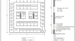
The idea of using recovered heat to replace a separate heat source suggests a potential for energy savings. HVAC system energy use projections performed for the top floor of a sample office building (see Fig. 1, above) using the ASHRAE TC 4.7 Simplified Energy Analysis method[1],[2] show that heat pumps will not necessarily save money or energy.
The Simplified Energy Analysis method is a bin calculation that assumes the load for each zone varies linearly between a diversified peak cooling load in the highest temperature bin to a peak heating load in the lowest temperature bin. The diversified load calculation is similar to a peak load calculation for design, but the diversified calculation uses average solar gain based on percent possible sunshine instead of peak day solar heat gain. It also recognizes that internal heat gains offset heat loss through the building envelope during occupied hours.
Two systems were modeled in five cities with different climates:
- Rooftop VAV with 100% outside air economizer for free cooling (except no economizer in Houston because the economizer did not save energy) and perimeter hot water baseboard heat from a gas fired hot water boiler;
- Ground source heat pumps with a loop pump but no cooling tower or supplementary heater and an energy recovery ventilator that delivers a constant ventilation air quantity during occupied hours. A traditional water source heat pump with a cooling tower for heat rejection or a boiler for supplementary heat would have higher energy use.
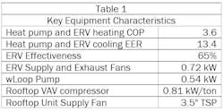
Table 1 lists key equipment characteristics for the systems modeled.
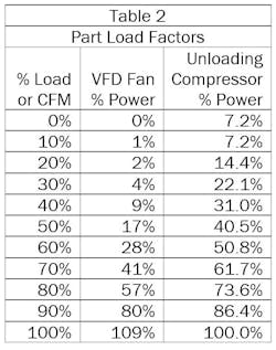
Table 2 lists the part load factors used in the calculation for fan and compressor load reduction.
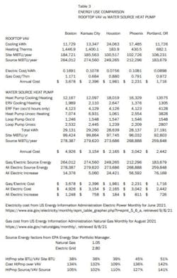
Table 3 summarizes projected HVAC system energy use for a ground source heat pump system compared to rooftop VAV in five representative U.S. cities. The data gives rise to several observations:
- In all five climates, the heat pump system uses considerably fewer BTUs at the site than the VAV system. The ratios range from 36% in Kansas City to 51% in Houston. The BTU savings at the site result primarily from the heat pump heating COP of 3.6 compared to less than 1 for a gas boiler. The differences are big enough that even a traditional water source heat pump system with cooling tower and electric boiler might use fewer BTUs at the site than a rooftop VAV system;
- Despite using many fewer BTUs, the annual energy cost for the heat pump system is considerably higher in all five cities. The increased cost ranges from 9% in Houston to 42% in Portland. The ratios make sense because Houston is cooling dominated so gets little benefit from the lower cost/BTU of natural gas compared to electricity. The cost differentials would increase with a traditional water source heat pump system;
- In Boston and Kansas City, the heat pump system source BTUs are only a few percent more than the rooftop VAV source BTUs. However, in Portland, the heat pump system uses 41% more source BTUs than the rooftop VAV system. Therefore, as long as an appreciable amount of electricity comes from fossil fuel sources, all electric systems are not likely to reduce source energy use or carbon equivalent.
The energy use projections show that when considering a heat pump system for energy savings, it is important to define how those savings will be measured. Lower site energy use does not necessarily translate into lower operating cost or lower source energy use/carbon equivalent.
VARIABLE REFRIGERANT SYSTEMS
Variable Refrigerant Flow (VRF) or Variable Refrigerant Volume (VRV) systems are increasingly popular for high efficiency, all electric heat pump applications. Newer products overcome some of the obstacles that previously limited the use of these systems: Systems can now provide heat down to single digit outdoor temperatures. Also, ducted fancoils with fans that can accommodate pleated filters and distribution ductwork are now available.
One remaining hurdle is that VRF and VRV system equipment, piping, and controls are specific to each manufacturer. With conventional split systems, engineers can readily use a Brand C, J, or T condensing unit with an air handling unit from just about any manufacturer. However, at this time, it is not possible to use a Brand M fancoil on a Brand D VRF or VRV system, either new or as a replacement. The controls will not communicate, and the piping might not be compatible.
VRF and VRV systems are not always backwardly compatible. If a compressor fails in a 10‑year old conventional system, it often makes economic sense to replace the entire condensing unit. Equipment design changes might preclude the option to replace an entire VRF or VRV outdoor unit instead of replacing the compressor - the electronics and controls of the new outdoor unit might not be compatible with the old fancoil units.
Some engineers are unsure about compliance with ASHRAE Standard 15, Safety Standard for Refrigeration Systems, and Mechanical code section 1103 when applying variable refrigerant flow systems.
ASHRAE Standard 15 limits the volume refrigerant in a system when a leak could discharge refrigerant into an enclosed space. In a system with multiple evaporators connected to one outdoor unit, a leak in one evaporator could discharge the entire system refrigerant volume into a single space. For the R‑410A refrigerant commonly used in the VRF systems, the limit is 25 pounds of refrigerant per 1000 cubic feet of space volume. That limit keeps the refrigerant concentration below 130,000 ppmv in case of a major refrigerant leak.
Refrigerant volume varies with system size, number of fancoils, and piping length, but 3½ to 4 pounds/ton of refrigeration capacity is a reasonable estimate. At 3¾ pounds of refrigerant/ton and a 15-ton system, the smallest enclosed space would have to be at least 2250 cubic feet in volume (250 square feet for a 9-foot ceiling) to meet the 25 pounds/1000 cubic feet limit without special provisions like emergency ventilation.
Some engineers rely on dilution by outside air from mechanical ventilation (such as a heat recovery ventilator) to increase the allowable refrigerant volume because dilution air would keep the refrigerant concentration below the 130,000 ppmv limit. An ASHRAE official interpretation (15-2007-3) disagrees on the basis that the ventilation system could be off (or failed) at the time of a refrigerant leak. The general consensus seems to be to use smaller systems when rooms are small to adhere to the Standard 15 refrigerant volume limits.
CONCLUSIONS
Ground source, traditional water source, or VRF/VRV, heat pumps offer advantages that engineers can consider when selecting a system. Cost of energy and source energy use/carbon equivalent might not be among them.
Any all-electric HVAC system can be carbon free at the building, but all electric systems are not truly carbon free if any of the electricity that runs them comes from fossil fueled generation.
##########
[1] Knebel, D, Simplified Energy Analysis Using the Modified Bin Method, RP-363, ASHRAE, 1983
[2] Kusuda,T and Sud, Update: ASHRAE TC4.7 Simplified Energy Analysis Procedure, ASHRAE Journal, July 1982, 33-39.
##########
A member of HPAC Engineering’s editorial advisory board, the author is both a mechanical and electrical engineer, as well as in-house counsel for Energy Economics, Inc., a consulting engineering firm based near Boston MA. He can be reached at [email protected].


