What is the proper valve arrangement off a high-pressure steam boiler, especially as it relates to safety and code compliance?
To begin, one must understand the thermodynamics involved in the pressurized heating of water. In Table 1, a typical steam table, note that when heat is applied, water temperature rises and, in a sealed pressure vessel, so does the pressure corresponding with that temperature. This is referred to as “saturated pressure,” or the limit of water to remain a liquid before changing state and becoming a gas (steam).
Note, too, if saturated water suddenly is released to atmosphere, much of it will flash to steam while expanding 1,600 times in volume. Thus, if the temperature of 15 lb of steam is 250°F, the temperature of 100 lb of steam is 338°F and rises as pressure increases. A third-degree burn occurs at 130°F for 30 seconds.
With this as the basis of understanding, we can address specifics as they impact both safety and code compliance.
Looking first at compliance, we reference two ASME (The American Society of Mechanical Engineers) codes: one for the manufacture of high-pressure steam boilers, Boiler and Pressure Vessel Code (Section I), and one for external piping, B31.1, Power Piping. This article focuses on the latter because it addresses not only piping requirements, but valves and fittings, which need to be employed to maximize safety.
Pressure and Temperature Factors
When considering external piping and fittings for high-pressure steam boilers, one must consider not only the pressure to which the valves or fittings will be exposed, but the maximum temperature, which may not correlate with the pressure. Such a case are valves and fittings applied to superheaters. In this case, the outlet temperature from a superheater will not correlate with the pressure; the temperature will be higher because of the sensible energy (heat) added to the steam.
Thus, the steam valves and fittings leading from the boiler to the main header must have a design pressure rating no less than the lowest set pressure of any safety relief valve on the boiler and a temperature rating comfortably above that steam temperature. The code does not give a specific temperature rating; it only infers the temperature rating of the device must be sufficiently high to mitigate any compromise based on overheating.
Flanges
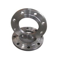
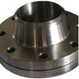
Flanges to be applied to piping beyond the outlet connection of a high-pressure steam boiler can be either slip-on (Photo A) or weld-neck (Photo B). Their application, however, has limits that need to be observed to be in compliance with ASME B31.1. Paragraph 104.5.1 of the code states slip-on flanges can be applied up to 24-in. nominal pipe size, but only on pressure classes of 150 and 300. All other conditions require weld-neck flanges.
Valves
If a high-pressure steam boiler has a manway allowing steam entrance and is commonly connected to a main steam header or other source of live steam entry, two steam valves are required off of the outlet.
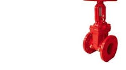
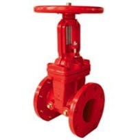
These valves must be rated as noted under “Pressure and Temperature Factors” above, be gate type, and be of outside-screw-and-yoke (OS&Y) construction so as to allow visual indication of the position of the valve (open or closed). Photo C shows a valve in the closed position.
When two valves are required, ASME B31.1 states a free-flowing drain line and valve must be installed between them and piped to a place of safe discharge with no possible obstructions.
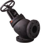
Often, a non-return (check) valve is supplied as the first of the two valves off of a boiler outlet. The other stop valve is upstream of it to provide shutoff and isolation from the main steam system, should the non-return valve need servicing. The non-return valve (Photo D) also is used to automatically cut an idle boiler back into a live steam header once its manual gate has been opened upon the boiler reaching approximately 85 percent of the common header pressure.
This non-return valve operates according to a pressure-and-velocity principle, opening when boiler pressure exceeds line pressure and closing when boiler pressure drops below line pressure. The velocity of steam through the valve is important to keep the valve from “chattering,” which causes excessive wearing of the seat. This often means the non-return valve is sized to be one to two pipe sizes smaller than the boiler outlet connection, with an adaptive reducer employed for this purpose.
It is very important to consult the boiler manufacturer regarding reducer and non-return-valve sizing so as not to exceed the boiler’s outlet-nozzle velocity limits. If the limits are exceeded, water-line instability and damaging carryover can result.
Safety Is All-Important
Earlier, this article explained some of the basic thermodynamics involved in boiler operation when water inside of a pressure vessel is heated and pressure is allowed to rise. Water becomes very hot and explosive as it reaches saturation and becomes steam as latent heat is added. Severe concussive scalding and even death can result if specific procedures are not followed.
Boiler manufacturers, the engineering community, and regulatory bodies go to extremes to protect operating personnel from the potentially devastating effects of hot-water and steam exposure. Throughout the manufacturing process and in the field, codes are enforced by inspectors operating in compliance with regulations developed by The National Board of Boiler and Pressure Vessel Inspectors. Though it may be the inspectors’ job to keep people safe, they are greatly assisted by boiler operators and facility engineers who continually educate themselves on safe and resource-efficient boiler operation and maintenance.
So, take advantage of training and continuing-education opportunities. Training leads to knowledge, and knowledge is power.


