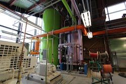
High-temperature-hot-water (HTHW) systems have been in use in Europe, serving residential and commercial heating needs, since the early 1900s. As technologies improved and stronger materials were developed, HTHW systems gained traction in the United States. Today, they are applied stateside on campuses where large amounts of heat need to be distributed without the maintenance hassles of steam.
HTHW systems typically operate with supply temperatures of 350°F and greater. The system pressure usually is set approximately 25 psi above the saturation pressure of the operating temperature. System pressure is critical to prevent water from flashing to steam and to avoid pump cavitation.
The main advantages of HTHW systems over steam systems are larger system temperature differentials and fuel savings. Larger system temperature differentials allow for greater thermal-energy storage. A HTHW system can withstand campus load swings, helping to maintain steady boiler firing rates. Additionally, HTHW systems are closed-circuit systems, which eliminate the need for boiler blowdown and reduce makeup-water requirements compared with steam systems. Lastly, the large temperature differentials of HTHW systems allow for smaller piping and equipment compared with steam systems.
There are four main components of HTHW-plant design:
- HTHW-generator selection.
- Pump selection.
- Consideration of system expansion and makeup.
- Stress analysis and piping layout.
This article will discuss all four for a recently completed HTHW-plant expansion at George Mason University in Fairfax, Va.
Background
In early 2013, George Mason University had four HTHW generators with approximately 110-MMBtu-input and 90-MMBtu-output capacity. With a growing student body and campus, the university needed additional heating capacity. The existing plant was operating at maximum capacity, so the university decided to expand it. The expanded plant would house the HTHW generators, primary pumps, secondary pumps, an expansion tank, a makeup tank, makeup pumps, compressed-air systems, HVAC systems, and all required piping and ancillary equipment. The addition would be able to be isolated from the existing plant equipment and still serve HTHW to the campus.
HTHW-Generator Selection
The most critical component of the design of the plant addition was the HTHW generator. The university’s HTHW system typically operated at 360°F and supplied water with a 100°F temperature differential (260°F return temperature). The system-pressure setpoint was approximately 220 psig. A new HTHW generator capable of providing these same operating conditions was desired.
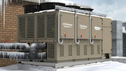
The university had had issues with tube failures in previous generators, so the selection of a new generator was of utmost importance. HTHW generators have a specific design; firetube boilers and traditional watertube steam boilers should not be utilized for HTHW service. HTHW generators force water through a specific flow path—via tube layout or orifices—to balance flow and ensure equal distribution of water. After careful consideration, a HTHW generator with a maximum output capacity of 25 MMBtuh was installed (Photo A).
Part of what influenced the selection of the generator was the burner, which had to be capable of utilizing natural gas and No. 2 fuel oil—all of the existing HTHW generators utilized natural gas as the primary fuel and No. 2 fuel oil as backup. With both fuels, efficiency and emissions were important to the university. The generator was specified with emission limits of 30-ppm nitrogen oxide and 50-ppm carbon monoxide on natural gas and efficiencies of 82 percent on natural gas and 84 percent on No. 2 fuel oil. Meeting these emission and efficiency requirements requires precise control of the burner. The burner utilizes jackshaft control. To control emissions, flue-gas recirculation and a stack damper were installed. To maintain setpoints and proper firing rates, the generator utilizes loop controllers. While a large amount of tuning was required to ensure proper burner flame and emissions, the generator achieved efficiencies of 82 percent on natural gas and 84 percent on No. 2 fuel oil. Additionally, all emission requirements were met.
It is important to note the HTHW generator does not utilize a typical stack economizer. Instead, it includes an “internal economizer” section of tubes. As with a traditional stack economizer, return water enters at the rear of the generator, where flue gases are hottest. The return water picks up energy from flue gas exiting the generator, ensuring maximum efficiency.
Pump Selection
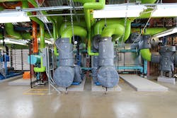
The HTHW plant utilizes a primary-secondary pumping configuration. The primary pumps (Photo B) ensure full flow through all of the HTHW-generator tubes at all times. This is critical to operation; if the generator does not receive minimum required flow, the system will be at risk of overheating, which could result in the hot-water supply temperature rising too close to saturation pressure, as described above. The secondary pumps modulate to maintain differential pressure measured at remote building locations.
PHOTO B. Primary HTHW pumps.
George Mason University’s HTHW pumping system is unique. While the system utilizes both primary and secondary pumps, the setup is not traditional: The secondary pumps are on the return side of the distribution system, meaning return water enters the secondary pumps first. With the system set up in this fashion, all pumps receive the lowest-temperature return water possible, which helps to increase the life and prevent the failure of pump mechanical seals.
The pumps are end-suction models. The mechanical seals have a carbon-silicon-carbide rotating face and a silicon-carbide-tungsten-carbide stationary face and are rated to 400°F. While the pumps receive lower-temperature water than they would in a traditional primary-secondary system, return-water temperature still varies from approximately 230°F to 300°F. Each pump includes a seal-cooling system utilizing a heat exchanger and chilled water to reduce water temperature at the pump seals. This seal-cooling system is critical to the operation and reliability of the pumps.
System Expansion and Makeup
One of the most important parts of the HTHW-plant addition was the installation of a 6,000-gal. expansion tank. The tank was sized so that all existing, new, and future HTHW generators could be operated off of it. This was particularly critical considering the existing expansion tank was nearing its maximum capacity.
There are two main types of expansion-tank pressurization that can be utilized in a HTHW system: steam and inert gas. Steam pressurization typically is utilized when an expansion tank can be installed at a high elevation and where there are steam demands. The university had neither, so inert-gas pressurization was selected.
With inert-gas (nitrogen, in the case of George Mason University) pressurization, the expansion tank can be installed at the same elevation as the HTHW generators. The expansion tank was connected to the return-water header. This allows the system-pressure setpoint to be maintained lower than if the tank were on the supply side of the system.
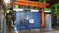
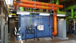
To ensure no system-overpressure conditions, a control valve was installed on the expansion tank to relieve HTHW to a new 700-gal. makeup-water tank (Photo C). The control valve opens on high system pressure. When HTHW is relieved to the makeup tank, it flashes to the atmosphere. With proper control of the HTHW system, the expansion-tank control valve should never open; however, it is required to in the event of unexpected pressure spikes in the system.
Stress Analysis and Piping Layout
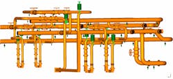
When designing a HTHW plant, it is important to take into account the thermal stress on the piping system attributed to piping configuration, design temperatures, and system pressures. Because of the high supply temperatures, the piping will move greatly from its installed location. To alleviate concerns of piping expansion on the George Mason University project, a thermal-stress analysis was performed. The computer program used system temperature, pressure, pipe size, pipe material, support location, and more to create a model showing deflections, pipe stresses, forces, moments, and other results. It is important to note that all stress results were calculated per ASME B31.1, Power Piping.
The thermal-stress analysis was a key part of the plant design for a number of reasons. First, the piping system needed to meet stress requirements of ASME B31.1. The pipe was laid out to allow system expansion where possible to reduce system stresses. Second, the boiler inlet-flange and outlet-flange forces and moments needed to be analyzed. To ensure flange loads were within HTHW-generator-manufacturer tolerances, pipe loops and spring hangers were installed on the piping system (Photo D). Additionally, the HTHW pump-flange forces and moments were evaluated. Pump manufacturers allow minimal forces and moments on their flanges. When forces are too large, pumps are at a greater risk of failure. This includes misalignment and pump-casing failures. To reduce forces and moments, bellows expansion joints, along with spring hangers, were installed on the suction and discharge of all HTHW pumps. By utilizing a combination of spring hangers, expansion joints, and pipe loops, an ASME B31.1-compliant piping system was designed and installed.
PHOTO D. Software model showing piping system with spring hangers and supports.
Summary of Design and Installation
In summary, there are many important components of a HTHW system. When designing one, remember to:
- Review HTHW design and operating conditions.
- Select a generator designed specifically for HTHW systems. A steam boiler retrofitted for HTHW operation may fail prematurely.
- Select pumps suitable for HTHW duty.
- Ensure the system has adequate pressurization and makeup capability.
- Perform stress and flange-loading analysis.
By following these steps, you can ensure proper HTHW-system components are specified and that a fully functional HTHW system is constructed. The HTHW-plant addition at George Mason University was completed in 2016, is fully operational, and is expected to play a major part in serving the campus’s heating needs for many years to come.
Eric Chrencik, PE, is a mechanical engineer with experience in central-plant and HVAC-system design and construction administration. He develops designs for steam, chilled-water, and high-temperature-hot-water central-plant and distribution systems for higher-education, government, and health-care facilities. He has experience with building hydraulic models and thermal-stress analysis. He can be reached at [email protected].
Did you find this article useful? Send comments and suggestions to Executive Editor Scott Arnold at [email protected].


