Although heat exchangers usually are selected for unique sets of conditions, sometimes it is of interest to know how they will respond to changes in inlet temperature. For example, it might be necessary to predict the change in cold-side outlet temperature resulting from a change in inlet boiler-water temperature or steam pressure. Because when one terminal temperature is changed, the others become unknowns, it is impractical to predict performance by means of the standard heat-transfer-rate equation:
q = (UA)(∆Tlm)F (1)
where:
q = heat-transfer rate
U = overall heat-transfer coefficient
A = heat-transfer-surface area
∆Tlm = log-mean-temperature difference (LMTD) of the two fluids
F is the LMTD correction factor for non-counterflow operation. It also is the ratio of surface area required with pure-counterflow operation to surface area actually required. It varies from unity (e.g., in plate-type heat exchangers and steam-water applications) to about 0.75, below which surface requirements tend to be impracticably large. Without a rate equation not involving LMTD or F, new temperature profiles for rated heat exchangers would be found through tedious trial of leaving temperatures until the known values of UA were satisfied—that is, until:
q ÷ [(∆Tlm)F] = UA (1a)
Fortunately, there is a rate equation not involving LMTD or F. It is based on the concepts of heat-transfer effectiveness (ε) and number of heat-transfer units (Ntu) and gives q as a function of the difference between the two entering temperatures. It is a consequence of the ε-Ntu method developed by W.M. Kays and A.L. London1 for the design of lightweight heat exchangers with complex geometries for use in aircraft and ships. This article outlines the method and provides examples illustrating its usefulness to HVAC designers.
THE ε-NTU METHOD
Heat-transfer effectiveness is defined as:
ε = (qa ÷ qt) = (actual heat transfer ÷ theoretical maximum heat transfer) (2)
Actual heat-transfer rate is given by heat balance:
qa = Ch(T1 - T2) = Cc(t2 - t1) (3)
where:
Ch, Cc = flow-stream-capacity rates of hot and cold fluids, respectively, defined as mass rate of flow times specific heat
T1, T2 = hot-side entering and leaving temperatures, respectively
t1, t2 = cold-side entering and leaving temperatures, respectively
The fluid-capacity rates and general temperature profile of all of the heat exchangers discussed in this article are represented by the following notation:
T1 → T2 Ch
t2 ← t1 Cc
From the general temperature profile, it is evident that fluid-temperature difference in a heat exchanger can be no greater than (T1 - t1). Moreover, no more heat can be transferred than can be absorbed at the cold-side capacity rate, Cc, and released at the hot-side capacity rate, Ch. And the maximum theoretical heat transfer cannot exceed the theoretical value attainable if the fluid with minimum capacity rate, Cmin, could experience the maximum temperature difference, (T1 - t1). So, regardless of which side has the minimum capacity rate, the theoretical maximum heat-transfer rate, qt, is given by:
qt = Cmin(T1 - t1) (4)
From equations 2, 3, and 4:
ε = [Ch(T1 – T2)] ÷ [Cmin(T1 – t1)] = [Cc(t2 – t1)] ÷ [Cmin(T1 – t1)]
When Ch is Cmin:
ε = (T1 – T2) ÷ (T1 – t1) (5)
When Cc is Cmin:
ε = (t2 – t1) ÷ (T1 – t1) (6)
Thus, given ε, T1, and t1 and the fluid-capacity rates, T2 and t2 always can be found.
Combining equations 2 and 4 results in a rate equation not involving LMTD:
qa = εCmin(T1 – t1) (7)
Number of heat-transfer units, or “heat-exchanger size,” is defined as:
Ntu = UA ÷ Cmin (dimensionless) (8)
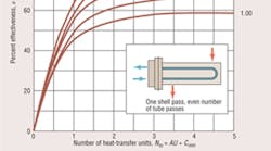
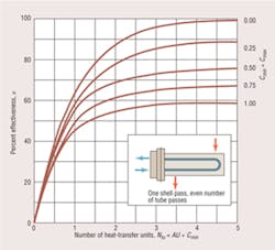
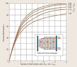
To show the relationship between Ntu and ε, Kays and London1 introduced capacity-rate ratio (Cmin ÷ Cmax) and plotted ε-vs.-Ntu curves for a large number of heat-exchanger types. Figures 1 and 2 show the curves for two exchanger types commonly used in HVAC design.
In re-rating an exchanger at new fluid temperatures, too little information is available to accurately predict the new U value. For moderate changes in average fluid temperature, however, the variation in U is unlikely to exceed the normal range of error expected in detailed heat-transfer calculations or even sophisticated computer programs. In most cases, the U value at the cataloged rating can be assumed valid for the new rating without serious error.2 With Ntu assumed constant, the actual U value does not have to be known because it is implicit in the Ntu. (See Equation 8.) This is especially applicable to hydronic systems because of the relatively small change in the heat-transfer properties of water.
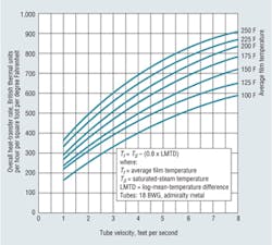
If there is reason to believe that a U value will be significantly different at new conditions, a design value can be used for a new Ntu, and a new ε can be found from curves such as those in figures 1 and 2. Figure 3 is useful for estimating variations in U over a range of average film temperatures. Changes in flow rates can, of course, affect U values significantly. Their effect can be calculated by methods found in standard texts. For this article, however, fluid-capacity rates are assumed to be constant.
EXAMPLES
In the following examples, English engineering units are used. Water is assumed to have a specific heat of 1.0 and a weight of 8.33 lb per gallon. In most of the examples, a “hydronic constant” of 500 (8.33 multiplied by 1.0 multiplied by 60 [minutes per hour]) is used to obtain fluid-capacity rate in British thermal units per hour per degree Fahrenheit (Btuh/°F). The heat-transfer coefficients were chosen for illustrative purposes only and are not necessarily the values one would calculate using the detailed procedures given by Kern4 and others.5
Shell-and-tube heat exchanger, T1 and T2 unknown. Consider a shell-and-tube heat exchanger with a catalog rating of:
Boiler water:
200 gpm 210°F → 180°F Cmin = (200)(500) = 100,000 Btuh/°F
Process water:
300 gpm 160°F ← 140°F Cmax = (300)(500) = 150,000 Btuh/°F
A system-design change requires the leaving temperature, t2, to be 180°F, with a return temperature, t1, of 150°F. Find the new T1 to satisfy this requirement. The new temperature profile to be completed is:
T1 → T2
180°F ← 150°F
Assuming there will not be a significant change in U, find ε from the catalog rating, and use it for the new rating.
From Equation 5:
ε = (210 – 180) ÷ (210 – 140) = 0.43
From Equation 3:
qa = (150,000)(180 – 150) = 4,500,000 Btuh
and:
(T1 – T2) = (qa ÷ Ch) = 4,500,000 ÷ 100,000 = 45°F
From Equation 5:
(T1 – t1) = [(T1 – T2) ÷ ε] = 45 ÷ 0.43 = 104.7°F
T1 = 150 + 104.7 = 254.7°F
T2 = 254.7 − 45 = 209.7°F
The new temperature profile is:
255°F → 210°F
180°F ← 150°F
Note that while U was assumed constant, its actual value did not have to be known.
Although the heat-transfer rate went from 3,000,000 Btuh ([100,000][210 - 180]) to 4,500,000 Btuh, there was no increase in heat-transfer-surface area. That followed from the assumption of a constant Ntu. Thus, from Equation 1a:
UA = q ÷ [(ΔTlm)F] = constant
For a change in q, there must be a proportional change in LMTD so that UA remains constant.
Semi-instantaneous water heater, new steam pressure. Consider a semi-instantaneous water heater with the following catalog rating:
25-psig steam in shell 267°F ↔ 267°F
100 gpm in tubes 120°F ← 50°F
The notation ↔ indicates isothermal condensation of saturated steam.
If this water heater has 40 sq ft of heat-transfer surface, what steam pressure would be required to produce a cold-side outlet temperature of 140°F at a maximum U value of 450 Btuh per square foot per degree Fahrenheit (Btuh/sq ft/°F)?
From Equation 3, noting that Ch is Cmax:
Cmax = [qa ÷ (T1 – T2)]
But for an isothermal process, T1 minus T2 equals 0; thus, Cmax is infinitely large, and Cmin divided by Cmax equals 0.
The temperature profile to be completed is:
T1 ↔ T2 Cmax = ∞
140°F ← 50°F Cmin = (100)(500) = 50,000 Btuh/°F
Because the design U value for the new conditions will not necessarily equal the value at the catalog rating, Ntu must be calculated.
From Equation 8:
Ntu = [(UA) ÷ Cmin] = [(450)(40) ÷ 50,000] = 0.36
From Figure 1, using the curve for Cmin divided by Cmax equals 0, ε equals 0.32.
From Equation 6:
T1 – t1 = [(t2 – t1) ÷ ε] = [(140 – 50) ÷ 0.32] = 281.3°F
Thus:
T1 = 50 + 281.3 = 331.3°F
From standard steam tables, the steam pressure at 331°F is 89 psig. The new temperature profile is:
Steam, 89 psig 331°F ↔ 331°F
Water, 100 gpm 140°F ← 50°F
Rating an exchanger for use with a propylene-glycol solution. A shell-and-tube heat exchanger with 80 sq ft of heat-transfer surface is available for service hot water for a small solar heating system. The design calls for a 50-percent-by-volume propylene-glycol solution to enter the shell from the solar panels at a rate of 100 gpm and an average temperature of 150°F. Service water in the tubes will enter from a hot-water storage tank at an average temperature of 110°F. The specific heat of the 50-percent glycol solution (taken at 120°F) is 0.87. The density is 64.1 lb per cubic foot, or 8.6 lb per gallon. The overall heat-transfer coefficient is an estimated 250 Btuh/sq ft/F. What will the heat-transfer rate and outlet temperatures be?
The temperature profile to be completed is:
100 gpm, 50-percent PG:
150°F → T2 Cmax = (100)(0.87)(8.6)(60) = 44,892 Btuh/°F
50 gpm, water:
t2 ← 110°F Cmin = (50)(500) = 25,000 Btuh/°F
Capacity ratio = Cmin ÷ Cmax = 25,000 ÷ 44,892 = 0.56
From Equation 8:
Ntu = UA ÷ Cmin = (250)(80) ÷ 25,000 = 0.80
From Figure 1:
ε = 0.50
From Equation 7:
qa = 0.50(25,000)(150 – 110) = 500,000 Btuh
From Equation 3:
t2 = t1 + q ÷ Cmin = 110 + 500,000 ÷ 25,000 = 130°F
T2 = T1 – (qa ÷ Cmax) = 150 – (500,000 ÷ 44,892) = 139°F
Thus, the design temperature profile will be:
150°F → 139°F
130°F ← 110°F
Plate-and-frame heat exchanger, new t1. A plate-and-frame heat exchanger with 4,600 sq ft of plate surface was ordered for an indirect free-cooling system designed to provide water to a conditioned space at a rate of 2,400 gpm and a temperature of 60°F when furnished with cooling-tower water at a rate of 1,800 gpm and a temperature of 56°F. An increase in air-conditioning load requires a delivered-water temperature of 58°F and a return temperature of 67°F, based on an overall U factor of 650 Btuh/sq ft/°F. If the flow rates are to be maintained, what does the temperature of the cooling-tower water (t1) need to be?
The new temperature profile to be completed is:
67°F → 58°F Cmax = (2,400)(500) = 1,200,000 Btuh/°F
T2 ← t1 Cmin = (1,800)(500) = 900,000 Btuh/°F
The cooling load is:
(1,200,000)(67 – 58) = 10,800,000 Btuh
Because there is no operating experience to verify the original design temperatures, use Equation 8 to establish effectiveness:
Ntu = [(UA) ÷ Cmin] = [(650 × 4,600) ÷ 900,000] = 3.3
Cmin ÷ Cmax = 900,000 ÷ 1,200,000 = 0.75
From Figure 2:
ε = 0.84
From Equation 6:
t1 = T1 – [(t2 – t1) ÷ ε]
From Equation 3:
(t2 – t1) = (qa ÷ Cmin) = (10,800,000 ÷ 900,000) = 12°F
Thus:
t1 = 67 – (12 ÷ 0.84) = 52.7°F maximum inlet temperature
t2 = 52.7 + 12.0 = 64.7°F
The new temperature profile is:
67°F → 58°F
64.7°F ← 52.7°F
Note that a “temperature cross” (t2 greater than T2) occurs. This is possible only with counterflow exchangers and is one of the reasons why plate-type exchangers are ideal for close-approach applications, such as free cooling.
Design of a new exchanger. To illustrate the ε-Ntu method's value in design, consider the calculation of surface area for a U-tube exchanger with 10-psig steam condensing in the shell and water at a rate of 450 gpm heated from 165°F to 210°F in the tubes. Assume a U value of 500 Btuh/sq ft/°F.
From standard steam tables, at 10 psig, the saturated-steam temperature is 240°F. Thus, the temperature profile to be satisfied is:
Steam at 10 psig:
240°F ↔ 240°F Ch = Cmax = ∞ (See second example.)
Water, 450 gpm:
210°F ← 165°F Cc = Cmin = (450)(500) = 225,000 Btuh/°F
For steam to water:
Cmin ÷ Cmax = 0
From Equation 6:
ε = (t2 – t1) ÷ (T1 – t1) = (210 – 165) ÷ (240 – 165) = 0.60
From Figure 1:
Ntu = 0.91
From Equation 8:
(UA) = (Ntu)(Cmin) = (0.91)(225,000) = 204,750 Btuh/°F
Thus:
A = 204,750 ÷ 500 = 410 sq ft
The duty can be found from Equation 3 or Equation 7. From Equation 7:
qa = 0.60(225,000)(240 – 165) = 10,125,000 Btuh
COMPARISON WITH THE LMTD METHOD
It is interesting to compare the calculation above with the LMTD method. The LMTD of the terminal-temperature differences, (T1 - t2) and (T2 - t1), is found from:
ΔTlm = (ΔTl – ΔTs) ÷ ln(ΔTl ÷ ΔTs)
where:
ΔTl = the larger terminal-temperature difference
ΔTS = the smaller terminal-temperature difference
The terminal-temperature differences are:
(T2 – t1) = (240 – 165) = 75°F = ΔTl
(T1 – t2) = (240 – 210) = 30°F = ΔTs
Thus:
ΔTlm = [(75 – 30) ÷ ln(75 ÷ 30)] = 49.1°F
As noted earlier, LMTD correction factor for non-counterflow operation, F, is 1.00 in steam-to-water applications because one fluid stream is isothermal. Thus, from Equation 1:
A = [10,125,000 ÷ (500)(49.1)] = 412 sq ft
If this had been a water-to-water application, several additional steps would have been required to evaluate F. These are not necessary with the ε-Ntu method, which is based on thermodynamic principles requiring no correction factor.
CONCLUSION
The ε-Ntu method not only eliminates calculation of LMTD and its correction factor, it can predict a heat exchanger's performance from one set of conditions to another, even when final temperatures and LMTD are not known. It is convenient for answering the what-if questions that often accompany heat-exchanger applications. In predicting how an exchanger in a hydronic system will respond to a change in inlet temperature, the heat-transfer product implicit in the Ntu of the cataloged rating usually can be assumed to remain constant over the extrapolation. Although there is a loss of accuracy, it usually is not significant, thanks to the relative stability of the thermal properties of water.
ACKNOWLEDGEMENT
While assuming full responsibility for any errors that may be found in this article, the author wishes to acknowledge the patient reading and constructive criticism volunteered by Kenneth M. Elovitz, PE, Esq.
REFERENCES
-
Kays, W.M., & London, A.L. (1955). Compact heat exchangers. New York: McGraw-Hill.
-
Guyer, E. (Ed.). (1989). Handbook of applied thermal design. New York: McGraw-Hill.
-
Potter, P.J. (1949). Steam power plants. New York: The Ronald Press Co.
-
Kern, D.Q. (1950). Process heat transfer. New York: McGraw-Hill.
-
McAdams, W.H. (1933). Heat transmission. New York: McGraw-Hill.
The president of James Breese & Co., Jim Breese represents manufacturers of heat-transfer equipment and provides design services to facilities engineers. He has a bachelor's degree in mechanical engineering from the University of New Mexico.
Did you find this article useful? Send comments and suggestions to Executive Editor Scott Arnold at [email protected].
