Years ago, as a technical leader in the utilities group of a large company, I was sent to an industrial facility in the Southeast to test the combustion efficiency of two 120,000-PPH steam boilers as part of a plan to reduce stack emissions and bring the boilers into compliance with new stricter emissions requirements.
During a preliminary inspection of the boilers and auxiliary systems, I noticed both of the 100-hp boiler feedwater pumps were running. That was not normal. The boilers were installed as a 100-percent-redundant system. The steam load averaged 70,000 to 90,000 PPH from summer to winter. Generally, one boiler was to be in service and the other in standby mode using a continuous-blowdown heat-recovery concept to keep it warm at line pressure. I knew from visiting the facility previously the boiler feedwater pumps also were intended to be 100-percent redundant. With a steam load of 90,000 PPH, there was no good reason for two pumps to be operating. I went to the control room to further review the distributed-control-system data and to talk to the utilities crew.
One operator informed me both boiler feedwater pumps had been in service for several months. I then recalled a visit to the facility about a year earlier, when the maintenance foreman approached me with concerns about the pumps’ performance. After inspecting the pumps, I suggested the foreman consider a minor overhaul because of the pumps’ age. The pumps were of two-stage, horizontal, split-case, double-suction design. I indicated the repair procedure was easy and straightforward: Remove the casing upper half; check the impeller eye, wear rings, and casing cutwater for erosion; and, if everything looked normal, repack the glands.
I asked the boiler operator if the maintenance foreman had taken my advice.
“Yes, last summer during the annual outage,” he said. “They found nothing abnormal, other than worn packing.”
Plant steam pressure was 215 to 225 psig. With one pump in service, feedwater pressure normally was 340 to 360 psig. Each pump was rated for 290 gpm at 720 ft. The deaerator operated at 7 psig (233°F); however, it was installed on the roof of the boiler building with a pump elevation head of 30 ft. There is no way cavitation should have been an issue with these pumps (40-plus ft of total suction head).
I asked the operator why both pumps needed to run.
“One pump could not maintain boiler drum-level and header pressure during sudden steam-load changes,” the operator replied.
Two pumps in parallel could double the feedwater flow or increase the pressure to near the maximum shutoff head of 360 psig at 50-percent flow rate, I thought.
My next action was to conduct another inspection and gather more data. In the motor control center, both pumps were pulling 82 to 85 amps (about 75-percent motor load).
Feedwater flow certainly appeared high. Bottom blowdown valves were closed and cold, as were the bottom header drain valves. We seemed to have a combined feedwater flow of about 440 gpm for a steam load of 90,000 PPH. Each pump (at 220 gpm) was about 53-percent efficient and using a combined 148 hp.
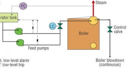
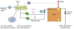
Each pump has a 1-in. line before the discharge check valve that returns to the storage section of the deaerator (Figure 1). These lines provide a minimum continuous flow of 10 percent (about 30 gpm, in this case) to protect against a no-flow condition inside of the pump when the steam-drum-level control valve automatically closes. Because the feedwater is 233°F, the lines are fully insulated and, thus, difficult to discern by an unseasoned operator.
It took me a few minutes to locate the orifice-plate assembly about 3 ft above the pump casing. The aluminum-jacketed lines were about 3 in. in diameter, and some of the insulation appeared new. I retrieved a screwdriver from my combustion-analyzer tool kit to conduct a quick flow-velocity sound test. With the pointed end of the screwdriver against the recirculation-line pipe and the handle against my ear, it was quite apparent the flow velocity was much higher than reasonable. Upon returning to the control room for further discussion with the operator, I learned both lines had developed leaks (at 90-degree elbows) over the previous year. The operator understood the lines were intended to protect the pumps from seizure, but was unaware of the location of the restrictive orifice used to set the flow rate.
It was now time to speak with a staff engineer. The pumps file and piping schematics were not easily found. The drawings indicated a stainless-steel orifice plate between flanges and an orifice diameter of 0.135 in. for the 1-in. lines. I suspected the orifice plates were severely eroded, which easily could have caused well over 120-gpm flow back to the deaerator tank (remember, feedwater pressure was about 340 psig).
I proposed a quick field trial:
1) The boiler operator was asked to close the 1-in. isolation valve (located before the orifice flange assembly) in the recirculation line of both pumps temporarily. Immediately, the load on both motors dropped from 82 to 46 amps.
2) After a few minutes of steady-state flow, Pump 2 was shut down. The amps on Pump Motor 1 increased from 46 to 73, about normal for one-pump operation at 70-percent boiler load.
3) Operation was switched to Pump 2, with similar results seen.
4) Pump 2’s minimum-flow line was opened. Motor load increased to 86 amps.
Without question, the orifice plates had eroded away. (The boilers were, after all, 30 years old.) After the boiler operator reminded us a sudden change in steam load (from a process heating cycle) could cause the boiler to trip, it was back to two pumps.
The Solution
Having seen this plate-erosion condition at other plants, I offered the following replacement orifice-pipe design for the recirculation lines:
1) Take 6 in. of 1¼-in.-diameter cold-rolled-steel-bar stock.
2) Drill a 9/64-in. hole through the center of the bar.
3) Employ a 1-in. National Pipe Thread Taper thread into both ends of the nozzle. Couple the nozzle into the existing line (threaded ends).
A tightly threaded joint (using Teflon tape) was effective for the Schedule 80 recirculation line and will last indefinitely.
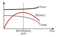
We prefer not to use automatic-recirculation-control (ARC) valves on low- and medium-pressure boilers with feed pumps of 100 hp and below. Generally, orifice pipes are more reliable and economical. At boiler loads below the 25-to-40-percent range, a feedwater pump will operate on the “flat part of the curve” (Figure 2). An ARC valve simply is not accurate enough to detect a pressure-differential change of 1 to 2 psig when a drum-level control valve closes. Note the flat head curve near shutoff in Figure 2.
An ARC valve converted to an electronic controller (using motor amps) does not work reliably either. Here, again, amperage change is difficult to discern at low feedwater flow rates. Failure of the valve to open (and establish minimum flow) is a recipe for pump cavitation and becoming “steam bound.” If a boiler trips on low water, plant production is affected immediately. (Repeatedly tripping a major process offline because of boiler-feedwater-pump mechanical issues is not good for one’s career path.)
With large boilers with high-capacity, high-horsepower feed pumps, ARC valves often are used to conserve energy. Not continuously pumping 10 percent of feedwater back to the deaerator reduces a lot of motor power over a year, especially in regions of the United States where power costs are 8 cents to 12 cents per kilowatt-hour. Just be cautious about dry-running a $50,000, multistage, stainless-trimmed feedwater pump. Talk about having an upset boss! (Been there, done that.)
Conclusion
Plant engineering and maintenance replaced the orifice plates in the recirculation lines with robust orifice pipe nozzles. The plant went from two pumps consuming 148 hp to one pump consuming 65 hp, saving approximately $100 in electrical power a day, with no subsequent troubles.
If your low- or medium-pressure boiler is experiencing a puzzling feed-pump-performance issue, be sure to include the minimum-flow-recirculation line in your investigation. If needed, consult a utilities guru.
The president of JoGar Energy Services, provider of on-site technical reviews, inspection services, and training seminars, Gary W. Wamsley, PE, CEM, has more than 40 years of plant-operation and management experience in the tire, aerospace, and paper industries. He is a member of ASME, the Association for Facilities Engineering, the National Society of Professional Engineers, and the Association of Energy Engineers, as well as HPAC Engineering’s Editorial Advisory Board.
Did you find this article useful? Send comments and suggestions to Executive Editor Scott Arnold at [email protected].


