By JAMES V. REUTER, III, P.E.
Reuter Consulting Engineers LLC
Baton Rouge, LA
There are many central cooling plants in operation, serving college campuses, hospitals, arenas, and other large facilities using chilled water as the cooling media. The primary-secondary-tertiary pumping system is most often the method employed to distribute the chilled water.
The primary side of the system is usually confined to the central plant, where chillers and pumps are looped together, while the secondary loop distributes the chilled water to outlying buildings and the respective tertiary loop circulates chilled water within the buildings. The system was originally based on constant flow volume in the loops. Each loop is decoupled, and the pressure in each loop is independent of the rest of the other loops on the campus.
Selecting chillers with large chilled water temperature differences (ΔT) allows for a decrease in the amount of chilled water flow required and reduces pumping costs, pipe size, and increases chiller efficiency. Chillers are often selected for ΔT = 16°F with 42°F supply water temperature and 58°F return water temperature. Selecting the chillers at higher ΔT makes sense from an operating standpoint, as reduced costs are always welcomed.
In the past, it was beneficial to have at least one chiller for off-peak loads as older chillers operate most efficiently at full load. Currently, variable-speed chillers are most efficient at partial load and allow for operation at less than full load conditions, allowing for effective off-peak performance.
On the tertiary loop, however, most of the air handling units in the chilled water system are selected on a 10°F or 12°F degree ΔT. The Air Conditioning and Refrigeration Institute (ARI) coil ratings are based on a ΔT of 10°F. This temperature difference provides for a reasonable flow rate for control while the low entering supply water temperature allows for sufficient dehumidification at the cooling coil. Chilled water is piped through the cooling coil in counter flow and controlled through the control valve, which is typically 2-way modulating control. Modulating 3-way valves are often included to provide minimum flow for the chillers and VFDs.
CHILLED WATER DESIGN AND OPERATION
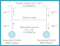
Chilled water is piped to each building, which under normal conditions the entering water temperature at the water coil in the air handling units is the chilled water temperature leaving the plant. Figure 1 illustrates the flow of water at the cross-over bridge piping under normal flow.
In this scenario, there is ample flow in the secondary loop and the pumps in the tertiary loop will distribute 2.4 GPM / Ton for ΔT = 10°F. When all the buildings on the system operate in this manner, there is 42°F chilled water supply and 52°F returning chilled water return to the central plant. However, the 52°F chilled water return temperature is lower than the 58°F setpoint and would indicate that there are too many chillers online and that the cooling capacity in the plant needs to be reduced. As chillers are shut off, the amount of flow in the secondary loop is reduced and less flow is available for each building.
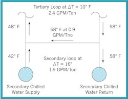
With less water available in the secondary loop at 1.5 GPM per Ton (16°F ΔT) the 2.4 GPM / Ton (10°F ΔT) buildings are restricted with supply water and make up the difference (0.9 GPM / Ton) through the common pipe at 58°F. This condition is shown in Figure 2.
The supply water temperature to the air units increases from 42°F to 48°F and the return water temperature is 58°F. The chilled water return temperature back to the central plant is right on target at design conditions and the system appears to be working fine.
TEMPERATURE ANALYSIS
With 48°F chilled water supplied to the cooling coils, the sensible cooling requirements can be met but latent heat requirements would be compromised. At 48°F the chilled water is not cold enough to dehumidify the air and, in a high humidity region, this can be devastating as the latent load is a large part of the total cooling load. Also, the premium that was paid to produce 42°F chilled water at the central plant has been wasted. There is a loss of 6°F, which represents 38% in the cost of operating the chillers. Also, the use of variable speed drives on pumps, 2-way control valves, and other devices cause the flow and temperature of the return water to change. Return water temperatures are usually monitored at the central plant to determine the load on the system; however, with these conditions, the return water temperatures do not reflect the true load on the campus and chillers are constantly being turned on and off to control the system capacity. The higher entering water temperature at the buildings is often blamed on excess heat transfer due to insulation breaks or other reasons and the real problem is frequently disguised.
CONCLUSION
The selection of varied operating temperatures can cause significant problems in large chilled water systems. These diversities can result in loss of chiller efficiency, humidity problems, space temperature control problems, and high operating and maintenance costs. The operating ΔT at the cooling coils in buildings should be selected to match the system ΔT. This design decision will allow the end-user to take full advantage of both system design temperatures to provide temperature and humidity control in the space, operating efficiency, and accurate monitoring of the load at the central plant.
To properly monitor the load on the plant, the chillers must be individually monitored to determine the current load and to decide which units to run. Digital chiller control and building management systems are designed for this operation, so control of the chillers online should be more accurately monitored.
Another important design issue is the decoupling of each loop. Proper design of the common pipe with no pressure drop will ensure that the loops are decoupled. When the loops are not decoupled, the piping is in series with the upstream loop. With all the pumps in series, the return water line will be at a higher pressure than the supply line and the water will have a reverse flow through the system. As with other chilled water problems, the space temperature setpoint might be met but humidity control will be compromised. Many alternative designs suggest various valves in the common pipe but the best design is to have no pressure drop across the common pipe.
Proper design of a primary-secondary-tertiary system is critical to its performance and requires the designer and the operator to have a thorough understanding of the system dynamics. I was told years ago that these systems are self-balancing. After years of application of these systems, I learned that they work properly only if they are designed correctly.
REFERENCES
Kirsner, W. (1995). Troubleshooting chilled water distribution problems at the NASA Johnson Space Center. HPAC Engineering, 67(2): 51-59.
Kirsner, W. (1996). The demise of the primary-secondary pumping paradigm for chilled water plant design. HPAC Engineering, 68(11): 73-78.
Primary Secondary Pumping Application Manual. Bell and Gossett. Published January 2013. Accessed December 3, 2017.
