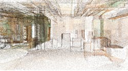
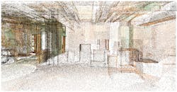
While we may not realize it, 3-D imaging is part of our daily lives. Every time we access Google Maps for directions to a new destination, for example, we are employing 3-D imaging. This same technology—or a variation of it, laser mapping—is now available for use by architects and engineers for surveying building conditions and exterior elevations, which then can be integrated into building information models.
Building information modeling (BIM) is used to cultivate and foster a client’s vision. With laser mapping, the effectiveness of BIM can be enhanced. Benefits of laser mapping include expedition of a design team’s efforts, field-investigation time savings, increased accuracy of field data with definition of actual location, reduced safety risk (personnel do not have to climb ladders or reach around equipment), and further development of client electronic files of existing conditions. One of the most significant benefits is that engineers can spend their time more effectively, addressing actual engineering issues, rather than drafting issues. Yet despite these advantages, many design professionals shy away from laser mapping because of a lack of understanding of what it is and how to incorporate it into a project.
With 3-D laser mapping, laser beams rapidly scan the shapes of objects, and the time for the beams to travel to each point on the objects is calculated. From this scan, point clouds—data points that each are given an “X,” “Y,” and “Z” coordinate—are developed. The more beams projected in a given area and time frame (density), the more defined an image will be, resulting in a better end product. Density can be varied based on how detailed the survey needs to be, along with how many target points are used. Density and number of target points correlate directly to the cost of a scan. The use of 3-D laser mapping, along with increased computer power, is making imaging technology more effective, more precise, and more usable across platforms.
Key Factors
The million-dollar question is how do you know if a BIM project is a good candidate for laser mapping. Key considerations are:
• Requirements. Has the owner or agency operating the building requested 3-D mapping? Increasingly, 3-D modeling is being required, especially by government agencies that have to maintain and operate buildings over many decades while administrating renovation projects. For many government buildings, CAD drawings are lacking, which makes identifying areas during the troubleshooting and concept phases difficult. In such situations, 3-D mapping can be particularly useful.
• Time and cost. What is the opportunity cost of not using 3-D laser mapping? When you consider the time it takes experienced designers to verify and document all existing conditions, especially with multiple utilities in a condensed area, 3-D modeling becomes much more cost-effective. The use of laser mapping frees up resources for valuable tasks, such as preparing preliminary calculations and developing conceptual layouts, and it expedites coordination of disciplines. Manipulation of a building information model to test-fit various design scenarios is paramount to productivity and quick client turnaround. Whether a project is of considerable size or has been fast-tracked, the time and efficiency benefits of using 3-D modeling can outweigh the expense of the technology itself.
• Product quality. Will laser mapping lead to a better end product? If a renovation is extensive and there are potential conflicts with existing utilities, 3-D laser mapping can make the design more accurate while minimizing cost overruns and delays.
Case Study
RMF Engineering Inc. and Waldon Studio Architects (WSA) used 3-D imaging to design the renovation of a 2,500-sq-ft area in the basement of a building on the campus of the National Institutes of Health (NIH) in Bethesda, Md. The project had a number of critical requirements, including the installation of a dedicated HVAC system, the raising of ceilings to accommodate large video screens, and minimal interruption of existing services and daily operations.
A detailed field survey was conducted to verify the routing and location of all existing utilities. Some of the utilities, such as domestic water and sanitary piping, are to remain in place, while others, such as supply and return ductwork and large electric and local-area-network conduits, are to be relocated to accommodate architectural renovations. The sprinkler piping, chilled water, and heating water are to be extended and connected to the new HVAC equipment.
The project was a great candidate for 3-D modeling because of the significant number of utilities (plumbing, chilled and hot water, laboratory services, ductwork) in a small area, as well as the extensive nature of the renovation. The design team was able to do basic project planning, such as perform preliminary calculations, develop conceptual layouts, and make major decisions regarding system selection, while the 3-D imaging was being prepared. This accelerated the design process by at least several weeks.
The laser-mapping process needs to be incorporated at the onset of a BIM project. For the NIH renovation:
1) A third party specializing in the use of laser-mapping equipment—TransCon Imaging Solutions—was brought in. Multiple scans were taken to identify the various utilities, which were stacked above one another. These scans were combined to create an accurate 3-D representation of the space. This part of the project, including setup, scan, and travel time, took less than a day. The more compact the utilities (and, of course, the larger the area), the greater the number of required scans.
2) Once the laser scan was completed, the data was sent to the design team and converted using BIM software. WSA cut sections through the point clouds and built all of the piping, ductwork, and equipment components. This took about three days.
3) The basic BIM product was delivered to the engineering team. RMF’s first task was to check the alignment of all of the images and make adjustments as needed.
4) Once the building information model displayed all existing conditions accurately, a follow-up field survey was conducted. The team identified the type of utility associated with each image in the point cloud, as well as properties of the utilities, such as type of piping and whether the piping was insulated. The follow-up survey was essential to addressing questions that could not be answered by the building information model.
The time spent developing a dimensional layout and routing all of the utilities was greatly reduced.
Without the use of 3-D imaging through laser mapping, the field portion of the project would have taken approximately two weeks. Instead, it took only about three days. Not only did laser mapping save time in the field, it saved time in creation of the model and increased the accuracy of the final documents. This saved both architectural and engineering time and helped to enhance coordination between the architecture and engineering teams. Because of the size, time frame, and complexities of the project, the use of 3-D laser mapping was well worth the expense.
Although construction on the NIH project has yet to begin, the information about the existing utilities obtained from the 3-D model is expected to help the construction team to avoid time delays and cost overruns attributed to existing conditions. This is especially critical with a client that, like NIH, wants to minimize downtime and remain operational throughout renovation.
Conclusion
As with all emerging technologies, as 3-D laser mapping becomes more refined and costs are reduced, use and effectiveness will increase. As the technology evolves, it will become another tool design professionals use to improve the quality of delivered products and increase efficiency.
An associate with RMF Engineering Inc., Stefan Domby, PE, LEED AP, has significant experience in the design and analysis of mechanical systems serving health-care, laboratory, institutional, federal, and industrial facilities. He routinely uses computer-modeling techniques to support his analysis and design of hydronic and process piping systems. His other areas of expertise include energy-system-performance modeling, chilled-water-distribution-system analysis, and engineering economic analysis. Mike Morgan, AIA, is a vice president of Waldon Studio Architects. As an architect and general design-build contractor, he has provided turnkey solutions affecting more than 400,000 sq ft and 2,000 people for projects totaling $13 million in design, renovation, and relocation services. His projects require strong team- and consensus-building skills and an ability to deliver practical, high-quality design solutions within strict budget and time constraints.
Did you find this article useful? Send comments and suggestions to Executive Editor Scott Arnold at [email protected].


