When it opened in 1972, Jordan Hall on the campus of the University of Virginia (U.Va.) in Charlottesville, Va., was a premier research facility. Nearly 40 years later, the HVAC infrastructure of the seven-story, 250,000-sq-ft building, home to the U.Va. School of Medicine, no longer could be maintained and was prone to regular failures. Experimental product and data were being lost, and operating costs were spiraling out of control.
In 2010, U.Va. hired RMF Engineering Inc. and DPR Construction to overhaul Jordan Hall's HVAC infrastructure. The work, which was to be performed while the building remained operational, included the replacement of eight 30,000-cfm air handlers, as well as the steam, reheat, and chilled-water systems and supply and partial-exhaust ductwork, and the addition of a major energy-recovery system. The most significant engineering and construction challenge was posed by the transition from 200 stand-alone exhaust fans to a central high-dilution-exhaust-fan system (Photo A).
The use of building information modeling (BIM) by the project team allowed the transition to occur in an organized manner clearly understood by the client, the contractor, and facility users.
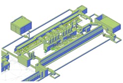
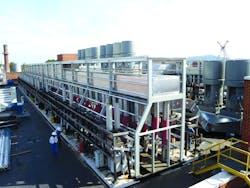
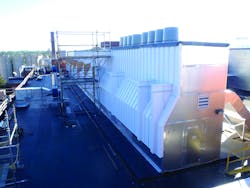
Each exhaust fan was modeled based on drawings made and measurements taken during field investigations. The project team devised a concept whereby an architectural enclosure would serve as a walkable corridor and an exhaust manifold connecting the 200 exhaust risers to eight new 40,000-cfm high-dilution exhaust fans (Figure 1). An existing vivarium exhaust system was not incorporated into the new manifold system partially because the vivarium staff wanted independent air systems. The vivarium system has a larger external static pressure that would have an adverse effect on the efficiency and energy use of the laboratory manifold system. Similar analysis was used to justify the two dedicated and independent dilution exhaust fans shown alongside the eight main dilution exhaust fans in Figure 1 and Photo B. These fans serve the anatomy laboratory, where the use of high-pressure-loss dissection tables makes the use of separate fans much more energy-efficient.
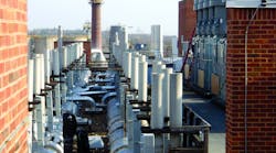
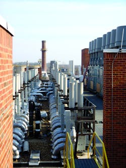
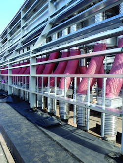
Working with the building information model, the design and construction team established a process for relocating 10 fans simultaneously through the use of industrial flexible ductwork and wooden platforms. This was necessary because the structural lattice for the architectural enclosure needed to be constructed where the original fans and exhaust-riser roof penetrations were located. The entire architectural enclosure was prefabricated through the use of BIM drawings. Ten-foot sections were lowered into place with a crane and bolted together. The top portion of the architectural enclosure serves as part of the exhaust ductwork. The exterior is constructed of the same insulated-foam injection panels used for the air handlers and dilution-fan exhaust plenums. Additional structural-steel framing (Photo C) was required because of wind loading at the top of the building. A final cladding was adhered directly to the exterior panels (Photo D). The roof of the enclosure was provided with an EPDM membrane to protect against water leaks at the 200 riser penetrations, a problem that had plagued the building in the past.
The dilution fans and associated plenums were installed first and connected to half of the exhaust manifold, allowing the point-of-use fans to be transferred to the manifold exhaust system.
The eight high-dilution exhaust fans formed the central distribution point for the new exhaust manifold system. The BIM structure for the dilution fans, provided by the manufacturer, served as the starting point. The operating external system static pressure was confirmed by determining the highest operating static pressure of the existing utility exhaust fans. The final operating static pressure incorporated the internal filters, heat-recovery coils, and isolation dampers of the system. Direct-drive fans were used to minimize vibration and reduce fan-belt and bearing maintenance.
Each fan essentially was replaced with an industrial-strength flexible connection (seen in yellow in Figure 1 and in red in Photo C) extended from the existing transite exhaust riser up to a premanufactured dampered connection on the exhaust manifold. The flexible ductwork had to be corrosion-resistant as well as rated for a minimum of 3 in. of negative static pressure. Each connection shown in Photo C was provided with an opposed-blade-damper section with a testing, adjusting, and balancing (TAB) section. As each existing exhaust fan was transferred to the manifold system, the previously connected riser's airflow was monitored to ensure it remained relatively constant. Each riser was out of service for approximately 30 min, while its point-of-use exhaust fan was converted. Fume hoods were tested through face-velocity measurement once airflow to the risers was restored. The fume hoods were put back in service at that time.
Motor-control centers for the existing 200 exhaust fans were located in small rooftop enclosures in close proximity to where the new dilution fans were to be located. These central electrical distribution hubs needed to stay operational throughout the phasing and transformation process. The central exhaust manifold system was designed in BIM to allow the removal of the motor-control centers. After a number of options were test-fitted with the help of BIM, four large exhaust connections were extended from each of the dilution-fan plenums up over the electrical enclosures into the exhaust-manifold mains. This process set the functional elevation of the architectural enclosure for the ductwork system. From an electrical-design perspective, the dilution fans were re-fed through an emergency feeder from the basement of the building, terminating in air-conditioned variable-frequency-drive vestibules attached to each of the dilution exhaust-fan plenums. This eliminated the need for a new motor-control center and simplified balancing of the exhaust risers.
Modeling the configuration of the enclosure allowed massing and architectural elements to be reviewed by the university and issues related to the incorporation of the exhaust manifold into the structure to be resolved. Organizing connections from the exhaust risers were coordinated quickly so that volume dampers could be adjusted, automated dampers replaced, and the like.
The final configuration includes two parallel architectural exhaust manifolds — one on each side of the high-dilution-exhaust-fan plenums. (Photo D shows one side of the nearly completed system.) This configuration, along with a redundant exhaust fan on each plenum, allowed the university's facility staff to maintain the new exhaust system without complete loss of airflow to a riser.
BIM helped the team to understand potential conflicts. The university's chief concerns were related to the rebalancing of the risers to keep up with churn. Those concerns were addressed with the TAB sections, which allow accessibility for accurate airflow readings. The design team envisions the installation of metering valves to automate the balancing system when funding becomes available.
In addition to design and engineering, BIM played a crucial role in project scheduling. DPR Construction incorporated construction-phasing requirements for the entire project into the building information model. This allowed the organization of thousands of tasks into a construction master plan, knocking months off of the original schedule.
An associate with RMF Engineering Inc., Stefan Domby, PE, LEED AP, has significant experience in the design and analysis of mechanical systems serving health-care, laboratory, institutional, federal, and industrial facilities, including use of computer modeling techniques. Recently, he completed work on two biomedical research laboratories at the National Institutes of Health in Bethesda, Md. The larger laboratory, which incorporates a state-of-the-art heat-recovery system and many specialty systems and was designed with an interstitial mechanical space to optimize flexibility for renovations, is the recipient of several national energy awards.
Did you find this article useful? Send comments and suggestions to Executive Editor Scott Arnold at [email protected].


