A client with a commitment to sustainability operates a three-story, 108,000-sq-ft commercial building in San Jose, Calif. The majority of the building’s cooling load comes from computers and high-power workstations that run continuously. The building is served by a chiller plant consisting of three chillers:
• The new 160-ton-nominal-capacity Chiller 1, which was installed to replace a 150-ton chiller.
• The 150-ton-nominal-capacity Chiller 2, which dates from the building’s late 1980s construction.
• The 190-ton-nominal-capacity Chiller 3, which was installed approximately 10 years ago to increase chiller-plant capacity. It shows wear and tear, but is reported to be in good working condition.
Three 15-hp chilled-water pumps, each rated for 350 gpm, serve a closed-loop chilled-water distribution system. In normal operation, two pumps and two chillers (chillers 1 and 2) run to circulate an average of 700 gal. of chilled water per minute to meet the building’s cooling load. In the pump room, a pressure-controlled bypass valve between the supply and return pipes maintains constant flow through the pumps and chillers. An override selector switch in the pump room provides three operating combinations: chillers 1 and 2, chillers 2 and 3, and chillers 1 and 3.
Because of its age and wear, Chiller 2 was targeted for replacement by the owner.
A recommendation that Chiller 2 be replaced with sustainable equipment that surpasses code-mandated levels of efficiency and provides control strategies to improve chilled-water-plant energy efficiency was made. This article describes the analysis behind that recommendation.
Methodology
During the peak cooling period of 2010, for two weeks beginning Aug. 26, the chilled-water plant was evaluated. At the time, chillers 1 and 2 were operating to meet the cooling load of the building. The facility staff reported Chiller 2 was unreliable and failed often. Indeed, Chiller 2 was deteriorated and appeared to be at the end of its useful life.
Cooling-load monitoring. Data loggers were installed on each chiller to record outside-air temperature, chilled-water supply and return temperatures, chilled-water flow, and power usage. The data loggers were set to collect data at 5-min intervals for the two-week monitoring period.
The chilled-water-plant control system allows the switching of chiller operation based on cooling demand. The facility staff was encouraged to keep Chiller 2 operational for as long as possible during the monitoring period.
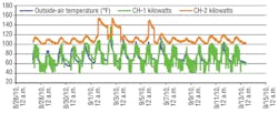
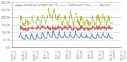
Chillers 1 and 2 ran continuously for the duration of the two-week monitoring period. Figure 1 shows the power usage of the two chillers. The chillers’ power-consumption curves match outside-air temperature. The average power consumption of Chiller 2 was almost 50-percent higher than that of Chiller 1.
In the absence of individual flow meters on the chillers and with identical entering- and leaving-water temperatures observed for chillers 1 and 2, equal flow distribution through each chiller was assumed. The deteriorated condition of heat-rejection surfaces indicated Chiller 2 efficiency had degraded significantly.
Ambient conditions exceeded design conditions (i.e., the measured load included the peak envelope cooling load) during the monitoring period. The average cooling load was 130 tons, with minimum and maximum demand of 103 tons and 155 tons, respectively. Because internal-process load variations did not correlate with outdoor-air temperature, the internal-process heat release1 was thought to have generated a consistent cooling-load demand independent of ambient conditions. Thus, measured load was a legitimate basis for selecting chiller cooling capacity.
Analysis of collected data suggested a 150-ton nominal chiller can provide ample cooling capacity for the building and handle the building’s cooling load for most of the year operating alone. Figure 2 shows the building’s cooling-load profile.
With a cooling load split evenly between chillers 1 and 2 assumed, Chiller 2 was determined to be operating with an energy-efficiency ratio (EER) of 8.4 at an average annual cost of $112,000.
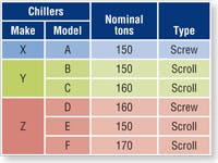
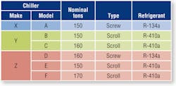
Chiller selection and sizing. Six air-cooled chillers from three major manufacturers (Table 1) were selected for evaluation. These models were chosen for their ability to provide approximately 150 tons of cooling capacity. Water-cooled chillers were excluded because:
• Installation of a water-cooled chiller would require significant changes to the layout of the chilled-water plant, as well as further design.
• The client’s corporate policy encourages water savings. Evaluation criteria were consistent with the client’s corporate policy:
• Chiller capacity.
• Sustainable refrigerant.
• Chiller efficiency (part-load performance and integrated part-load value [IPLV]).
• Price.
• Footprint.
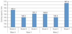
Chiller cooling capacity. Figure 3 shows net cooling capacity at Air-Conditioning, Heating, and Refrigeration Institute (AHRI) conditions (44°F leaving-water temperature, 54°F entering-water temperature, 95°F entering dry-bulb temperature) for the shortlisted chillers.
Sustainable refrigerant. Chiller 2 uses hydrochlorofluorocarbon- (HCFC-) based R-22 refrigerant. Considered an ozone-depleting substance, R-22 no longer is produced for or imported for use in new equipment in the United States and will be phased out of production completely by Jan. 1, 2020.2
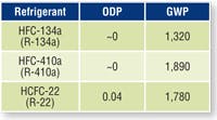
Hydrofluorocarbon- (HFC-) based refrigerants generally are considered more environmentally benign than HCFC-based ones. Table 2 compares the ozone-depletion potential and global-warming potential of some of the most popular refrigerants used in chillers.
R-134a and R-410a appear to be the most appropriate refrigerants for the client’s replacement chiller. Table 3 shows the refrigerant used in each of the evaluated chillers. Not only are the chillers in alignment with the client’s corporate policy, they comply with LEED Energy & Atmosphere Prerequisite 3, Fundamental Refrigerant Management.3Chiller efficiency. Developed by AHRI, IPLV uses four operating points (A, B, C, and D) with weighting factors intended to indicate the amount of time a chiller operates at different loads (100, 75, 50, and 25 percent) and assumed entering-dry-bulb (EDB) temperatures (Table 4). Because IPLV may not represent the actual performance of a chiller, this study compared part-load performance in addition to IPLV.
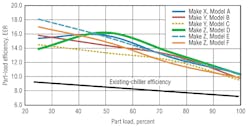
Figure 4 shows the part-load performance of each of the shortlisted chillers. Based on cooling-load data, the new chiller was expected to run at 50 to 75 percent of the load the majority of the time. Thus, selecting a chiller with high efficiency in this range was more important than selecting a chiller with a high IPLV.
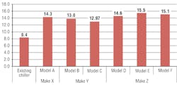
Between 50- and 75-percent load, the Make Z, Model D screw chiller had the highest efficiency. The Make Z, Model E scroll chiller, however, had the highest IPLV (Figure 5).
The analysis was based on information provided by the local representatives of the chiller manufacturers in 2009.
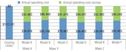
Operating cost. Figure 6 shows the annual operating costs of the shortlisted chillers calculated based on part-load performance. If the Make Z, Model D screw chiller continuously operated for a full year to provide 75 tons of cooling (approximately 50-percent load), the electricity cost would be approximately $58,400,5 a $12,000 savings over the Make Y, Model C scroll chiller; a $7,000 savings over the Make Y, Model B scroll chiller; and a $1,500 savings over the Make X, Model A screw chiller. It also would offer significant savings over the other Make Z models in the study.
The Make Z, Model D screw chiller was determined to offer the most energy savings and lowest operating cost for the facility.
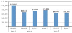
Capital cost. Figure 7 compares the manufacturer-provided unit costs6 of the six chillers.
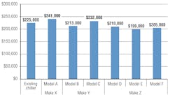
Owning-cost index. Figure 8 compares the owning-cost indices (OCI) of the six chillers. OCI is defined as the sum of first cost and operating cost for a number of years desired to recover the cost—in this case, two years. OCI for the existing chiller was $225,000; for four of the six new chillers, OCI was less. Because the Model D, Make Z screw chiller offered the lowest OCI, it was recommended to replace Chiller 2.
Incentives. Pacific Gas and Electric Co. provides incentives to manufacturers, not owners, of high-efficiency chillers. The incentive amount is $25 per ton for a chiller with an IPLV of 14.29 or higher and $44 per ton for a chiller with an IPLV of 15.1 or higher. At least one vendor indicated a willingness to share the incentive with the owner. The unit costs in figures 7 and 8 do not include incentives.
Chilled-Water Distribution System
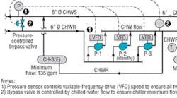
For chilled-water distribution, the plant utilizes a variable-flow system controlled by two-way valves at terminal units coupled to a constant-speed pumping system (Figure 9). Because the chillers operate continuously year-round, the system appears to be a good candidate for conversion to true variable primary flow via installation of variable-frequency drives (VFDs) on pump motors. Flow through the chillers and chilled-water system, then, would be varied based on system load in the most energy-conservative manner possible, significantly reducing the annual energy consumption of the chilled-water pumping system.
The minimum flows of chillers 1 and 3 are 135 gpm and 195 gpm, respectively. The minimum flow of the recommended replacement for Chiller 2 is 160 gpm. The chilled-water distribution system, then, should be modified to maintain a minimum flow of 195 gpm to allow Chiller 3 to operate alone, if needed (Figure 10).
Equipment datasheets showed the pumps were sized for 350 gpm at 105 ft of head. The pumps have 10.5-in. impellers and 15-hp motors with 1,750-rpm speed. The pump curve indicates 200-gpm falls within the pumps’ allowable operating range.
The local sales representative suggested the pump motors, installed during the early 1980s, would not be compatible with VFDs. The owner should either replace the existing pump motors with VFD-compatible premium-efficiency motors or replace both the pumps and the motors with VFD-compatible pumps and motors. This will ensure reliable operation of the pumps and reduce energy costs.
Control Strategy for Variable Flow
The current operating strategy of the chiller plant involves two chillers running continuously. The client indicated the internal load fluctuates, with minimal to no internal process load from the building for significant periods of operation.
Two options for modifying the operating strategy were recommended:
• One-chiller, one-pump operation. In the event of low cooling load, one chiller and one pump would operate. If less than minimum flow were required, a bypass valve would recirculate flow to maintain the minimum flow. This mode of operation would provide adequate cooling based on measured cooling loads, but not provide a hot standby, in the event a chiller failed.
• Two-chiller, two-pump operation. If the cooling load were to increase by more than 50 percent of the cooling capacity of one chiller, two chillers and two pumps would operate. This mode of operation is similar to the current operational strategy, which allows a second chiller to operate when one chiller fails.
It was recommended that pump-motor speed be controlled to maintain a constant static pressure at a pressure sensor located on the chilled-water supply pipe downstream of the bypass valve. This signal would be used to control the VFD on each pump so that all pumps operate at the same speed.
It also was recommended that bypass-valve operation be maintained to ensure minimum flow to each chiller and that the bypass valve be controlled by a flow sensor installed on the chilled-water supply downstream of the bypass valve. The bypass valve would open to maintain a minimum flow of 200 gpm when one chiller is operating and 400 gpm when two chillers are operating.
Following are estimated cost7 and energy savings:
• Replace motors with energy-efficient models: $2,244, 18,700 kwh.
• Add VFD control to the pumps, operate with two chillers: $9,814, 81,784 kwh.
The payback period for these modifications combined would be less than a year.
Conclusions
Table 5 summarizes the relative merits of each chiller evaluated.
Based on the above evaluation, it was recommended the existing chillers be replaced with the Make Z, Model D screw chiller. Further, it was recommended the chiller plant be modified from constant to variable volume. The distribution-system conversion would require:
• The installation of VFDs on pump motors. Pumps would be controlled by a pressure signal downstream of the chilled-water loop.
• Maintenance of minimum flow by changing the control of the bypass valve in the pump room from pressure to flow.
• The replacement of pump motors with VFD-compatible premium-efficiency motors.
• Modification of the operational strategy from two-chiller operation to one- and/or two-chiller operation.
The recommendations offer a solution that meets the client’s corporate sustainability goals and reduces energy costs significantly. Annual savings of approximately $54,000 and $12,000 are expected, if the recommended chiller is installed and the recommended chilled-water-distribution-system modifications are made, respectively.
Notes
1) For reasons of confidentiality, details of the process were not available. Thus, the data recorded during the two-week monitoring period are the only indication of internal-process load.
2) Source: www.epa.gov/ozone/title6/phaseout/hcfc.html.
3) Source: USGBC. (2010). LEED reference guide for green building design and construction. Washington, DC: U.S. Green Building Council.
4) Source: ANSI/AHRI Standard 550/590-2011, Performance Rating of Water-Chilling and Heat Pump Water-Heating Packages Using the Vapor Compression Cycle.
5) The cost of electricity was based on the average rate paid by the owner the previous year: 12 cents per kilowatt-hour.
6) The costs are rounded to the nearest thousand and do not include taxes and shipping.
7) All costs are in 2010 dollars.
A senior project manager for CDM Smith Inc., Arvind Akela, PE, CEM, LEED AP BD+C, has over eight years of experience in the planning, design, and construction of energy, water, and wastewater projects. His areas of interest include cogeneration, combined heat and power, energy efficiency, sustainability, and HVAC. He is a member of the Water Environment Federation and California Water Environment Association (CWEA) and serves on the board of directors of the San Francisco Bay Section of the CWEA. He has bachelor’s and master’s degrees in mechanical engineering.
Did you find this article useful? Send comments and suggestions to Executive Editor Scott Arnold at [email protected].
