Improving HVAC With PID and VFDs
Uncontrollable changes both inside and outside of a building can impact efforts to maintain the desired temperature. Changes in occupancy, lighting and computer equipment use, outdoor temperature, and the like can cause the set temperature in a building to fluctuate constantly.
This article discusses three functions of control that can be used to regulate the consistency of an HVAC system while surrounding conditions change: proportional, integral, and derivative.
- Updated Schneider Electric discussion on PID control (2018) available here.
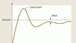
Proportional, integral, and derivative controls use a closed-loop feedback system to maintain a predetermined process level, or set point. Variation from the setpoint is referred to as process deviation, or offset error, and requires continuous corrective action for a process output to be maintained.
PROPORTIONAL-INTEGRAL-DERIVATIVE CONTROL
Proportional, integral, and derivative controls work together to maintain a constant temperature:
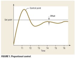
The proportional control function determines how quickly an output reacts to a process variation. It is a control algorithm in which, in the case of HVAC applications, air or water is moved to a position proportional to the deviation of the value of the controlled variable from the setpoint. Proportional control's effect on system startup is shown in Figure 1;
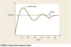
Integral control determines a reaction based on a sum of variations. Also known as reset response, it tends to correct offsets resulting from proportional control. Without integral control, a system may be unable to reach its target value. Proportional-integral (PI) control is a control algorithm combining the proportional and integral control algorithms;
Derivative control determines reactions to the rates at which process variations change and is very sensitive to measurement noise. It opposes any change and is proportional to the rate of change.
As a controlled variable deviates above or below its set point, PI control corrects the process deviation. The difference between proportional control and PI control is that proportional control is limited to a single control element for each value of a controlled variable, while PI control changes the final control element to accommodate load changes while keeping a control point at or very near its set point.
Reset is a proportional-control technique by which a secondary sensor resets the set point of a primary sensor. The reset action of the integral component shifts the proportional function around the setpoint as the load on the system changes, keeping the control point at the set point by correcting the control signal. Because offset is eliminated, the proportional function usually is set fairly wide to ensure system stability under all operating conditions. PI control's effect on system startup is shown in Figure 2.
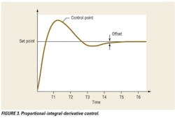
Proportional-integral-derivative (PID) control adds the derivative function to PI control. It enhances the PI control algorithm by adding a component that is proportional to the controlled-variable rate of change (derivative), compensating for system dynamics and allowing faster control response.
The farther a control point moves from its set point, the faster the corrective action the derivative function takes to bring it back. The closer a control point moves toward its set point, the slower the corrective action the derivative function takes to reduce the possibility of overshoot. PID control's effect on system startup is shown in Figure 3.
Overshoot is caused by a large offset at startup. Microprocessor-based PID startup may be enhanced-PID (EPID) control. Basic EPID functions are dependent on start value and error ramp time. Start value sets output at a fixed value at startup.
For example, a variable-air-volume-air-handling-system supply fan may have a start value of 20 percent. The start value is high enough to enable the fan to start, allow the fan motor to self-cool, and provide a proof-of-operation signal for a monitoring system.
For a heating, cooling, and ventilation air-handling unit (AHU), a suitable start value may be 30 percent because of the heating, ventilation (economizer), and mechanical-cooling demands of the AHU.
PID error (set point minus input) is ramped slowly into a PID regulator, which arrives at the setpoint without overshoot, undershoot, or cycling.
The weighted sum of proportional, integral, and derivative functions is used to correct process variation. With those three functions tuned, system performance can be controlled for responsiveness and oscillation.
VARIABLE-SPEED DRIVES
PID calculations adjust motor speed as necessary to maintain a set point. As system dynamics, such as valve and damper operation, ambient temperature, and flow rate, change, the motor speed required to maintain a set point differs. PID performance is based on the ability to maintain a set point, not on motor speed.
A variable-speed drive may be capable of serving as a PID controller. A set-point value can be provided by a wired signal to the drive's input/output terminals or sent by serial communications.
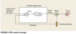
The use of PID control with a variable-speed drive is illustrated in Figure 4.
A variable-speed drive uses a reference set point to compare feedback. Scaling of PID parameters is required to suit the application or the range of the sensor providing the feedback signal (or both). Examples of PID parameters include 0- to 20-psi pressure, 0- to 500-gpm flow, and -100°F to 300°F temperature.
For variable-speed drives, speed reference-level parameters must be selected as a percentage of the analog voltage input range used as the feedback input signal. The output-frequency level is entered in hertz and set as a function of the speed reference, while the internal PID setpoint is entered as a percentage of the PID feedback range.
To simplify the setup of PID control for a variable-speed drive, values as close to the maximum limit as possible and that remain within powers of 10 with respect to actual values should be used.
UTILIZING PID CONTROL FOR HVAC APPLICATIONS
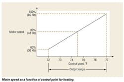
Proportional control provides the output capacity of HVAC equipment matching the load requirements of a building. Output capacity is controlled using a percent of full output or, in the case of motor speed, 0 to 60 Hz, similar to a two-position switch by which mechanical equipment is either fully on (100 percent) or fully off (0 percent).
HVAC applications with variable-speed drives benefitting from PID regulation include:
- AHUs
A pressure sensor placed inside of an air duct can provide feedback to a drive PID regulator, comparing desired pressure with actual pressure and optimizing by adjusting fan-motor speed.
- Chilled-water pumps
Chilled-water pump speed is controlled based on chilled-water-line-to-AHU-cooling-coil differential pressure. A pressure sensor can be placed in a chilled-water line so that a drive PID regulator can compare actual pressure with desired pressure and adjust chilled-water-pump motor speed to minimize variance.
- Cooling-tower fans
By adjusting cooling-tower-fan-motor speed, the speed of a cooling-tower fan and the temperature of water discharged from the cooling tower can be controlled to maintain a desired temperature set point.
BENEFITS OF PID CONTROL
Incorporating PID control with variable-speed drives results in HVAC systems that are more efficient and save money. Digital controls, throttling valves, and dampers that can be opened vary hot- or chilled-water-pump-motor speed or AHU-fan speed, allowing the temperature to be controlled. Savings can be realized in three major areas:
- Maintenance
Reducing dependence on throttling valves and dampers for the mechanical adjustment of airflow output saves on the maintenance of temperature-control equipment.
- Energy
Open-loop control equipment cycles on and off constantly, causing a peak in-rush current during startup. Closed-loop control saves energy by providing continuous operation of AC motors at lower speeds.
- Money
Reducing pump- and fan-motor speed reduces electricity costs.
Harvey Eure is a product manager focusing on enclosed variable-frequency drives for Schneider Electric. He can be reached at [email protected].