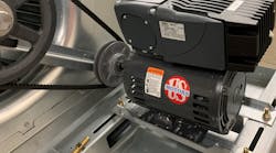
With the rising cost of energy, the use of variable-frequency drives (VFDs), also known as inverters, is growing. By optimizing electrical flow to an alternating-current (AC) motor, a VFD can provide substantial energy savings. Within the field of flow control, the potential for increased efficiency with VFDs is especially dramatic. Many centrifugal fans and pumps run continuously, often at reduced loads. Because the energy consumption of such devices correlates to their flow rates cubed, the motors driving them will use less power if controlled by a VFD. In fact, if a fan's speed is reduced by half, the horsepower needed to run the fan drops by a factor of eight. In constant-torque applications (reciprocating compressors, conveyors, mixers, etc.), in which more-accurate process control is the main objective, a VFD can be programmed to prevent a motor from exceeding a specific torque limit.
Currents induced on motor shafts by VFDs can wreak havoc with motor bearings, dramatically shortening motor life and causing costly repairs, even with motors marketed as "inverter-ready." One solution is to design systems with motors with built-in bearing protection. Minimal voluntary standards issued by the National Electrical Manufacturers Association (NEMA) for insulated-gate-bipolar-transistor- (IGBT-) inverter-controlled motors rated for 600 v or less state that such motors should be designed to withstand repeated surges of 1,600 v (or 3.1 times the motor’s rated voltage) and rise times of 0.1 microsecond.
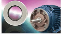
For VFD-controlled motors already installed, shaft grounding can be a cost-effective way to achieve sustainability.
How VFDs Can Cause Motor Failure
Typically, the most vulnerable parts of motors controlled by VFDs are windings and bearings. The cause of their damage is repetitive electromagnetic interference (EMI) arising from the non-sinusoidal current produced by a VFD's power-switching circuitry. EMI passed through wiring is known as high-frequency line noise, harmonic content, eddy currents, parasitic capacitance, capacitive coupling, magnetic dissymmetry, electrostatic buildup, high-voltage ringing, reflective voltage, overshoot, steep voltage wavefronts, and common mode voltage. EMI passed through radiated waves is known as radio frequency interference (RFI). These unwanted currents can cause degradation of insulation, bearings, coil varnish, etc., and lead to motor failure. Causes of such failure include high peak voltages, fast voltage rise times, the corona effect, and induced shaft currents.
High peak voltages arising from the high switching frequencies of modern VFDs are a major concern, especially if a single VFD is used to control multiple motors or if the line connecting a VFD with a motor is more than 50 ft long. As a rule, the longer the cable, the lower its impedance. If load impedance is higher than line impedance, current is reflected back toward the VFD, creating voltage spikes at the motor terminal that can be twice as high as the direct-current (DC) bus voltage.
Often overlooked until it is too late to save the motor, cumulative bearing damage is caused by VFD-induced shaft currents. Hard to predict but preventable, these currents are best addressed during the design of a system. Without some form of mitigation, shaft currents discharge to ground through bearings, causing unwanted electrical discharge machining (EDM) that erodes the bearing race walls and leads to excessive bearing noise, premature bearing failure, and subsequent motor failure.
A Closer Look at Bearing Damage
Short of dismantling a motor, there are two main ways to check for bearing damage: measuring vibration and measuring voltage. Because of the number of possible variables, neither method is foolproof. By the time vibration tests confirm bearing damage, it usually is too far advanced for the motor to be saved. If a baseline voltage measurement is taken right after a VFD has been installed, subsequent monitoring may provide early warning of harmful current loops.
Shaft currents can be measured by touching an oscilloscope probe to the shaft while the motor is running (Figure 1). These voltages repeatedly build up on the rotor to a certain threshold, then discharge in short bursts along the path of least resistance, which all too often runs through a motor's bearings.
Serious cumulative electrical bearing damage can be attributed to the extremely fast voltage rise times (dV/dt) associated with the IGBTs found in typical pulse-width-modulated VFDs. Discharge rate tends to increase with carrier frequency. Discharges through bearings can be so frequent that, before long, the entire bearing race wall becomes riddled with fusion craters known as frosting. Because many current motors have sealed bearings to keep out dirt and other contaminants, electrical damage has become the most common source of bearing failure in VFD-controlled AC motors.
In the phenomenon known as fluting (Figure 2), the operational frequency of a VFD causes concentrated pitting at regular intervals along the race wall, forming washboard-like ridges. Fluting can cause excessive noise and vibration that forewarn of imminent bearing failure.
The Search for a Solution
Motor failures caused by VFD-induced shaft currents can result in significant unplanned downtime. Additionally, these failures affect the performance and mean time between failure of the original-equipment systems in which the motors are used. In some production applications, even a momentary stoppage caused by motor failure can cost more than $250,000, excluding the cost of repairing/replacing the motor. Clearly, there is a need for a device that mitigates bearing damage from VFD-induced shaft currents.
Section IV, Part 31.4.4.3 of NEMA Standard MG1, Motors and Generators, recommends bearing insulation at one end of a motor if the NEMA-designated motor-frame size is 500 or larger and the peak shaft voltage is greater than 300 mv. In these larger motors, bearing damage may be caused in part by magnetic dissymmetries that result in circulating end-to-end shaft currents.
For smaller motors, Standard MG1 recommends insulating both of a motor's bearings with high-impedance insulation or installing shaft-grounding brushes to divert damaging currents. For these motors, a VFD can generate high-frequency common-mode voltage, "which shifts three phase winding neutral potentials significantly from ground," according to Standard MG1. Because the damaging voltage oscillates at high frequency and is capacitively coupled to the rotor, the current path to ground can run through one or both bearings.
Standard MG1 is quick to point out that bearing insulation will not prevent damage to other connected equipment. When the path to the bearings is blocked, the damaging current seeks another path to ground. That other path can go through a pump, gearbox, tachometer, encoder, or break motor, which consequently can wind up with bearing damage of its own. An ideal solution is one that redirects shaft currents along a low-impedance path from shaft to ground, protecting connected equipment as well as bearings.
Conclusion
Regardless of the application, the success of an automated control system depends upon its design. If in-house engineers lack the special expertise required, they should enlist the services of a qualified systems integrator who understands the engineering specifications, operating conditions, and performance curves of the entire system. With informed decisions at every stage from specification to commissioning, potential problems can be anticipated and resolved.
Especially important is the selection of VFDs and motors for such systems. They should be rated for compatibility with not only each other, but other components of the system. A savvy specifier will choose a motor that is equipped for use with modern fast-switching VFDs—one with adequate protection against bearing damage as well as winding damage.
Experienced in industrial product development and commercialization, Adam Willwerth is the development manager for Electro Static Technology. He has a bachelor's degree in management from the University of Maryland and a master's degree in business administration from Southern New Hampshire University.

