Unique Approach to High-Efficiency Laboratory-Exhaust Energy Recovery
Laboratories typically consume five to 10 times more energy per square foot than office buildings of similar size—in the case of specialty laboratories, sometimes more—with the disparity attributed mainly to higher HVAC loads from evermore stringent ventilation requirements. In laboratory facilities with large numbers of fume hoods and biosafety cabinets, meeting these requirements can be especially challenging, particularly in jurisdictions that do not permit the passage of hazardous containment air through high-efficiency total energy-recovery wheels. With alternatives such as run-around-coil loops, split passive heat pipes, and fixed-plate air-to-air heat exchangers typically having much lower recovery efficiencies, what is one to do when the use of total energy-recovery wheels is prohibited?
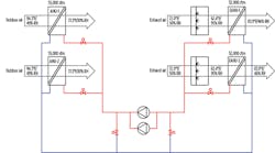
That was the question facing the team planning the renovation of the Rita Hollings Science Center (RHSC) on the College of Charleston campus in Charleston, S.C. The authority having jurisdiction (AHJ) prohibited the use of energy-recovery wheels, while thermal limitations regarding the central energy plant’s capacity necessitated the demand for chilled water be minimized. The project team responded by incorporating a high-performance networked run-around heat-recovery-coil loop system in conjunction with indirect adiabatic/evaporative cooling of exhaust air (Figure 1). Specialized energy-recovery coils in the exhaust-air stream transfer energy from exhaust air to a water/glycol fluid circuit piped to energy-recovery coils in the supply-air stream to precool outside air. With laboratory exhaust air adiabatically cooled prior to passing through the exhaust energy-recovery coils, cooling of the heat-transfer fluid is increased, which further cools outside air and maximizes recovery efficiency.
Code Implications
A manifold system consisting of fume-hood exhaust and general laboratory exhaust was chosen because of the desire to capture all potentially recoverable energy in one system. Though the types of research conducted within the building were well-defined, because of the evolving nature of research laboratories and the chemical and process changes within, the AHJ required the system be treated as a hazardous exhaust system as defined in Section 510 of the 2012 International Mechanical Code (IMC). Quoting Paragraph 510.4 of the 2012 IMC, the AHJ stated: “Contaminated air shall not be recirculated to occupiable areas. Air containing explosive or flammable vapors, fumes, or dusts; flammable, highly toxic, or toxic gases; or radioactive material shall be considered to be contaminated.”
Total energy enthalpy wheels—rotating wheels usually made of porous material in a honeycomb matrix pattern coated with a desiccant molecular sieve material that transfers both heat (sensible) and moisture (latent) energy between exhaust air and incoming outside air—typically provide the highest effectiveness and quickest life-cycle payback because of the transfer of water-vapor molecules. With the supply- and exhaust-air streams located next to each other and passing through opposite halves of the rotating wheel, however, separation is not complete, as the possibility of exhaust air bypassing at the interface between the air streams at the energy-wheel boundary and at the point at which the wheel passes from one air stream to the other exists. Cross contamination can be limited with the use of brush seals, pressure-differential purge airflow, and the use of 3-ångström (Å) molecular sieves (which prevents the transfer of materials larger than 3Å, but allows the transfer of water vapor at 2.8Å). It was the position of the AHJ, however, that the 2012 IMC requires zero cross contamination.
Heat-Recovery Options
With total energy enthalpy wheels prohibited by the AHJ, other methods of heat recovery, including split passive heat pipes, fixed-plate air-to-air heat exchangers, and run-around-coil loops, were evaluated.
A split passive heat-pipe system is a dedicated refrigerant piping loop with heat-recovery coils. The piping loop connects a finned-tube refrigerant coil in the exhaust-air stream to a finned-tube refrigerant coil in the outside-air stream. Through a natural thermosiphon process, refrigerant is circulated back and forth between the supply-air coil and the exhaust-air coil, where it changes from liquid to gas back to liquid. During winter, the refrigerant absorbs heat from the exhaust-air heat-recovery coil and transfers it to outside air. During summer, the refrigerant absorbs heat from the outside-air heat-recovery coil and transfers it to exhaust air. The transfer is sensible heat only, and there is no possibility of cross contamination; however, a maximum 30- to 50-ft equivalent horizontal separation is required, impacting ductwork layout and physical-space requirements.
Fixed-plate heat exchangers consist of alternating layers of plates that are separated and sealed; there are no moving parts. The majority of plates are solid, non-permeable, and arranged in a cross-current flow pattern. Exhaust air and supply air flow into alternating channels, passing near each other, but not touching or mixing. Sensible energy from the warm air flowing through one side of the exchanger is transferred to the cold air flowing through the other. The transfer is sensible heat only, and there is no possibility of cross contamination; however, fixed-plate heat exchangers are large and require the air streams to be next to each other, impacting ductwork layout and physical-space requirements.
The typical run-around heat-recovery system is a dedicated glycol piping loop with heat-recovery coils and circulating pump. The run-around loop connects a standard finned-tube hydronic coil in the exhaust-air stream to a finned-tube hydronic coil in the outside-air stream. During winter, the pumped glycol absorbs heat from the exhaust-air heat-recovery coil and transfers it to outside air. During summer, the pumped glycol absorbs heat from the outside-air heat-recovery coil and transfers it to exhaust air. The transfer is sensible heat only, and there is no possibility of cross contamination. An advantage of a run-around heat-recovery system is that the exhaust- and supply-air streams do not need to be near each other, minimizing ductwork-layout issues and physical-space requirements.
The RHSC had severe physical constraints that eliminated all but the run-around heat-recovery system. To maximize performance, indirect adiabatic/evaporative cooling of the exhaust-air stream was used in conjunction with the networked run-around heat-recovery-coil loop system.
High-Performance Run-Around-Coil Loop Design
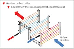
While a typical run-around heat-recovery system has one supply-air stream and one exhaust-air stream, a “networked” design allows several air-handling units (AHUs) and exhaust recovery units to be incorporated into one energy-recovery system through a common hydronic pumping loop. The networked run-around-coil hydronic loop for the RHSC consists of heat-recovery coils in the two exhaust AHUs, heat-recovery coils in the two supply AHUs, a common variable-flow hydronic circuit connecting all heat-recovery coils, and a skid-mounted hydronic module consisting of primary/standby pumps, coil control valves, and an advanced system controller. The heat-transfer medium is a water/glycol mixture to prevent freezing or frost damage. Unlike standard hydronic coils, which have a header on one side, the heat-recovery coils are specially designed with headers on both sides to balance pressure and flow and create near-perfect turbulent cross-counterflow current, resulting in closer approach-temperature differences between the exhaust/outside-air streams and the fluid circuit for maximum recovery efficiency (Figure 2). Protective corrosion-resistant coatings prolong the life of the exhaust-air-stream coils. Unlike standard run-around heat-recovery systems, which provide a constant fluid-circulation rate, the high-performance heat-recovery system is demand-dependent, with the controller varying fluid-circuit operation and flow to individual coils based on inputs from the building automation system (BAS), including airflow measurements from the supply and exhaust AHUs and the associated airflow temperatures. The demand-oriented networked design approach maximizes system efficiency by allowing all recovered energy to be used before any supplemental or new energy is added.
Indirect Adiabatic/Evaporative-Cooling Design
To increase heat-recovery effectiveness, exhaust air was cooled via indirect adiabatic/evaporative cooling prior to passing through the heat-recovery coil, resulting in an increased temperature difference between the air streams.
The indirect adiabatic/evaporative-cooling design of the exhaust system consists of makeup-water-treatment equipment, a high-pressure water pump, automatic control valves, a system controller, and water-atomization-type spray humidification manifolds in the exhaust AHUs upstream of the exhaust heat-recovery coils. In recognition of significant summer cooling-coil-condensation discharge from the 100-percent-outdoor-air laboratory AHUs, a 4,800-gal. rainwater and AHU condensate-collection system beneath the building, rather than municipal water, is the evaporative water source, which can approach 5 gpm during peak cooling periods. In automatic mode, the indirect adiabatic/evaporative-cooling-system controller maintains high-pressure water flow to individual spray humidification manifolds based on inputs from the BAS, including airflow measurements from the supply and exhaust AHUs and the associated airflow temperatures.
Energy-Recovery Effectiveness
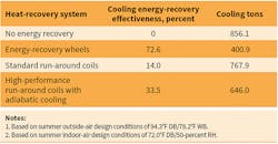
Using the RHSC’s airflow and temperature design conditions, the cooling energy-recovery effectiveness—defined by ANSI/ASHRAE/IES 90.1-2010, Energy Standard for Buildings Except Low-Rise Residential Buildings, as “the change in the enthalpy of the outdoor-air supply as a percentage of the difference between the outdoor-air enthalpy and the return/exhaust-air enthalpy at design conditions”—of the systems is given in Table 1 and shown in Figure 3.
While the use of energy-recovery wheels would have been the most effective option, it was prohibited by the RHSC’s AHJ, making high-performance run-around coils with adiabatic/evaporative cooling the most effective and feasible option. Compared with standard run-around-coil heat recovery, the system reduces chilled-water tonnage by 16 percent and minimizes the building’s impact on the campus’s central chilled-water system.
Conclusion
An energy-recovery system can reduce cost and laboratory energy use substantially. System selection is dependent on applicable codes as well as project goals and constraints, including spatial and financial obstacles. While high-performance run-around coils with indirect adiabatic/evaporative cooling can be a beneficial approach for some projects, it is not commonly utilized for a variety of reasons, including higher initial cost, dependence on a reliable water source (such as rainwater/condensate), and the fact some AHJs still permit the use of minimal- or no-crossover-contamination energy-recovery wheels with manifolded fume-hood exhaust. For some projects, such as the RHSC, however, adiabatic/evaporative exhaust cooling is an optimal addition to run-around-coil heat-recovery systems.
Craig Buck, PE, LEED AP, is a mechanical engineer and associate with RMF Engineering with extensive experience in the design of HVAC, plumbing, and gas systems for laboratory facilities. He is well-versed in design standards and code requirements associated with laboratory facilities, having successfully designed systems serving a wide variety of specialized areas within laboratory environments. He has worked on major laboratory projects for the University of Maryland, Virginia Polytechnic Institute and State University, Midlands Technical College, the Medical University of South Carolina, and the College of Charleston. He can be reached at [email protected].
Did you find this article useful? Send comments and suggestions to Executive Editor Scott Arnold at [email protected].
