A New Way to Analyze Fan Systems for Optimal Performance, Cost Savings
“There are only two qualities in the world,” playwright and critic George Bernard Shaw wrote, “efficiency and inefficiency.” In the industrial world, however, there is room for only one.
In industrial environments, efficiency is critical to success; downtime and unnecessary use of energy are to be avoided like the plague. Addressing design flaws prior to construction, avoiding risk, and implementing strategies that lower energy consumption are smart ways to minimize costs, limit impacts on schedules, and ultimately achieve efficiency.
System Effect
High-performance fan systems are essential to efficient industrial processes. Within the air-movement-and-control industry, most fans designed to provide critical ventilation in commercial and industrial facilities, such as laboratories, automotive plants, and semiconductor fabs, have been tested carefully by manufacturers to meet industry standards. Despite conscientious testing and precisely calculated ratings, however, many fans do not operate as anticipated after they are installed; they simply fail to achieve the flow and static-pressure rating indicated by the manufacturer’s performance curve. This leads to system inefficiencies and a derated system that must be addressed sooner rather than later, possibly affecting production and almost always increasing costs.
System effect—defined by ASHRAE as “a phenomenon that occurs in fluid systems (fans, pumps, and distribution systems) that can create undesired conditions that cause reduced capacities in all or part of a system”1—helps to explain why a fan that performs optimally in a laboratory does not perform as well in a facility. This gap in performance exists in large part because the countless configurations and conditions under which a fan will operate in a live facility setting cannot be replicated in a laboratory. Likewise, the tight environmental control characteristic of a laboratory setting cannot be duplicated in the field.
ANSI/AMCA Standard 210/ANSI/ASHRAE Standard 51, Laboratory Methods of Testing Fans for Certified Aerodynamic Performance Rating, defines requirements for the laboratory testing of fans. Achieving accurate, repeatable fan-performance ratings is a main goal of the publication. Because even the most carefully controlled testing cannot accurately predict system effect, a rating system is better viewed as a way to compare fan alternatives than as a pledge of performance.2,3,4
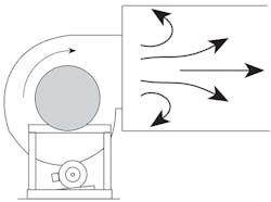
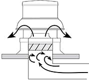
ANSI/AMCA Standard 210/ANSI/ASHRAE Standard 51 discusses the effect of inlet and outlet connections on fan performance. For maximum effect, air must enter and leave a fan uniformly, but this does not always happen in real-world applications. A fan that discharges too close to a wall or plenum can compromise system performance (Figure 1). Deficiencies in duct connections, even small ones, can affect fan performance and operating efficiency. Wear on impellers—rotors used to increase and decrease airflow pressure—can cause vibration that leads to damage or failure of bearings or the overall fan structure. Obstructions at the fan inlet, such as guards or dampers, sometimes in combination, also can cause losses (Figure 2). Elbows or “T” fittings set too close together, poorly placed dampers, and inlet spin attributed to duct design all can contribute to system effect.
Duct leakage, which leads to performance issues, energy inefficiencies, and cost implications, often is overlooked or minimized as a contributor to system effect. ASHRAE commissioned a study of government buildings in California. In many of the buildings, duct leakage was found to exceed 20 percent of design airflow.2,3,4
System effect can be invisible to even skilled mechanical engineers and air-movement-and-control experts. For instance, a designer or engineer may determine resistance occurring in ducts, filters, dampers, and elbows some distance from a fan, but inadvertently overlook obstructions near the fan,5 which will render his or her calculations inaccurate to one degree or another.
Air Movement and Control Association (AMCA) International recognizes the gap between laboratory fan ratings and actual field performance and is working to find ways to bridge the gap, suggesting four actions3 that ultimately could improve the efficiency and performance of air systems:
- Rewrite ANSI/AMCA Standard 210/ANSI/ASHRAE Standard 51 to alter the way inlet obstructions are handled.
- Establish a static-regain duct-design program.
- Add sensors that help to measure flow volume and power draw to air-system products.
- Provide guidance for best application of products to customers.
The most carefully implemented installations can fall short of maximum performance because of something as simple as a lack of communication. Say a designer selected the fan with the best discharge position for a given area. Prior to installation, the area was reworked, but the changes were not communicated to the designer. The fan now is wrong for the space. From the start, fan performance will be compromised, and system effects will begin to accrue. The system operator will think the system has the maximum performance capabilities stated by the design engineer, but the system, in fact, will have derated performance capabilities. This will introduce unforeseen risks of production shutdown, system inefficiencies, and equipment damage.
To compensate for system effects and achieve required airflow, operators often speed up fans. According to the National Environmental Balancing Bureau, a 20-percent increase in fan speed is common. This requires a fan-power increase of more than 70 percent, which drains energy and hastens wear on fan motors and other components.2,3,4
New Method
A method of accurately and clearly simulating a fan system, including all distribution components, recently was validated and implemented. The method uses software that effectively predicts fan-system performance. Because it calculates flow rates and pressures in entire distribution systems, rather than rely on assumptions, the software is inherently more reliable than traditional analysis methods.
Powerful and flexible modeling software works with computer-aided-drafting software to readily provide meaningful data. Decision makers have access to data on everything from actual system performance, including system bottlenecks, to system performance and enhancements under any number of configurations.
Following are ways the modeling software can be leveraged:
- During design, the modeling software can be used for option analysis. Operating specifics, such as maximum flow and pressure, can be uploaded and run through the modeling program for any fan under consideration. This helps clients understand how a particular fan would perform in their operation. If the fan would perform poorly, the client simply can select another. If the fan would perform merely adequately, the software can be used to fine-tune system details, such as ductwork layout and damper placement, to achieve optimum performance.
- The modeling software can be used to evaluate fan-system performance over time. This helped one client decide whether to add a new fan to an existing system to boost performance or invest in a new system. The client had four existing fans running at 10,000 cfm with 9-in. static pressure. When viewed through the modeling software at 100-percent demand, the fans achieved only 6,000 cfm with 9-in. static pressure because of existing system effects and distribution bottlenecks. This information helped the client evaluate the risk to overall operations if one of the fans were to fail and determine a corrective course of action, which involved ductwork-based solutions to reduce static-pressure requirements.
- The modeling software has been used to manipulate system details, such as fan placement, size, and system layout, to help clients determine the best balance between investing in a fan system and achieving a certain level of performance over time, based on projected operational demands.
With fans among industry’s biggest energy users, modeling software can be an indispensable tool for making cost-conscious, energy-efficient decisions.
To learn more about this approach, contact the authors at [email protected] and [email protected].
References
- ASHRAE. (n.d.). ASHRAE terminology. Retrieved from https://www.ashrae.org/resources--publications/free-resources/ashrae-terminology
- Smith, W. (n.d.). System effect cubed, part 1: The gap our industry needs to address. Retrieved from http://www.amca.org/feg/systemeffectscubed-1.aspx
- Smith, W. (n.d.). System effect cubed, part 2: How to close the gap. Retrieved from http://www.amca.org/feg/systemeffectscubed-2.aspx
- Smith, W. (n.d.). System effect cubed, part 3: AMCA’s leadership in fan efficiency regulation. Retrieved from http://www.amca.org/feg/systemeffectscubed-3.aspx
- Greenheck. (1999). Understanding fan system effects. Product Application Guide FA/101-99. Retrieved from http://www.greenheck.com/media/articles/Product_guide/system_eff.pdf
Christian Radulescu of Western Integrated Technologies has 10 years of experience in mechanical-engineering design, equipment fabrication, and testing, including providing complete engineering, design, and construction solutions for various industrial mechanical systems. He can be contacted at [email protected]. Gavin Kaleta, PE, LEED AP, of SSOE Group is an experienced mechanical engineer/design lead who specializes in high-technology base-build projects, including building expansions and complex cleanroom retrofits. He can be contacted at [email protected].
Did you find this article useful? Send comments and suggestions to Executive Editor Scott Arnold at [email protected].


