The Role of Fan Efficiency in Reducing Energy Use
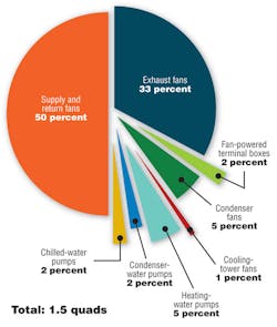
In the United States, HVAC systems generally consume the largest portion of a commercial building’s energy budget, with supply, return, and exhaust fans accounting for approximately 1.25 quads—or roughly the equivalent of 225 million barrels of oil—of energy use annually (Figure 1). Expected in the fall, the 2013 version of ANSI/ASHRAE/IES Standard 90.1, Energy Standard for Buildings Except Low-Rise Residential Buildings, will include a new fan-efficiency requirement based on ANSI/AMCA Standard 205-12, Energy Efficiency Classification for Fans. This article explores the role fan efficiency plays in Standard 90.1, with specific attention paid to how the new fan-efficiency requirement will work with the standard’s fan-power limitation.
Basics
Thermal loads and ventilation requirements determine the amount of airflow necessary to achieve HVAC performance targets. Fans provide the motive power to generate required airflow. Resistance to airflow is overcome by a fan through the addition of energy to an air stream. The rate at which energy is added to an air stream by a fan is called air power, which is calculated simply by taking the product of airflow rate and fan total pressure rise. Fan total pressure rise exactly balances system total pressure drop (see the sidebar “Fan Static and Total Pressure” below).
It is important to note that there is a significant difference between total pressure drop and static pressure drop in an air-distribution system. Except for the fan, airflow through an air-distribution system always is experiencing a total energy loss, largely because of air friction. This energy loss is represented by total pressure drop, not static pressure drop. Static pressure does not always decrease and may be exchanged for velocity pressure in duct expansions, in duct contractions, or at branches.
Likewise, fan efficiency is appropriately described by fan total efficiency, as this represents the ratio of energy delivered (air power) to power input at the fan shaft. The common practice of basing fan selection on fan static pressure is incorrect and will need to be reconsidered as energy conservation becomes more important.2
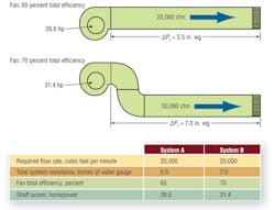
For a given operating point, airflow, and pressure, the fan with the highest efficiency will consume the least power. But simply selecting the most efficient fan does not ensure minimal energy consumption, especially when an air-distribution system is poorly designed and/or installed. For example, consider two competing systems with a 20,000-cfm flow requirement. System A has a total pressure drop of 5.5 in. wg, while System B has a total pressure drop of 7 in. wg because of inappropriately placed elbows (Figure 2). System A’s fan operates at 65 percent total efficiency, while System B’s operates at 70. At first glance, one might conclude the more efficient fan consumes less power, but that is not the case. Basic calculations show System A’s fan is consuming 26.6 hp, while System B’s is consuming 31.4. The difference is driven by the higher total pressure drop imposed by System B, not fan efficiency.
Minimizing total pressure drop through careful air-distribution-system design is the first step to ensuring minimum fan energy consumption. Think of a fan as the motor driving a system (load). The smaller the load, the less energy the motor must provide. Think responsible system design and careful installation first and selection of the most efficient fan second.
Existing Requirements
For many years, Standard 90.1 has imposed a fan-power limitation influencing both system design and fan efficiency. To illustrate, Option 2 in the fan-power limitation (Standard 90.1 Table 6.5.3.1.1A) requires net shaft power for all applicable fans in a system to be less than a specified maximum value. Equation 1 shows the requirement in generic form:
H ≤ αQ + A (1)
where:
H = fan-power limit, brake horsepower
α = coefficient dependent on system type (constant volume or variable volume)
Q = supply-air flow rate, cubic feet per minute
A = pressure-drop adjustment factor allowing certain system configurations and/or special components
In practice, all fans that supply, return, or exhaust conditioned air are included in the fan-power calculation. For this article, we will consider a simple system consisting of a single supply fan to illustrate the influence of the fan-power limitation on system design and fan efficiency.
Dividing both sides of Equation 1 by flow rate (Q) results in an expression for specific fan power (SFP) (Equation 2). When considering a single fan, it is important to realize SFP is equivalent to the ratio of fan pressure to fan efficiency:
SFP = (H/Q) = (PT/ηT) ≤ α + (A/Q) (2)
where:
PT = fan total pressure
ηΤ = fan total efficiency
For small values of SFP, fan total pressure (PT) must be low and/or fan total efficiency (ηΤ) must be high. Because fan efficiency always is less than 100 percent, the fan-power limitation effectively places an upper limit on fan total pressure, which is equivalent to system total pressure drop. Because this is equivalent to the ratio of system pressure to fan efficiency, system designers are encouraged to minimize system pressure drop and select a high-efficiency fan.
In the absence of pressure-drop adjustments (A = 0) and using the variable-air-volume (VAV) coefficient (α) of 1.3 hp per thousand cubic feet per minute (kcfm), as found in Standard 90.1, the maximum system resistance allowed for various fan selections can be calculated. For example, a system with a total pressure drop of 6.5 in. wg requires a minimum operating fan total efficiency of 79 percent to meet the 1.3-hp-per-kcfm requirement. Meanwhile, a system with a 2-in.-wg fan total pressure requires a minimum fan total efficiency of only 25 percent. The higher the system pressure drop, the higher the fan efficiency needed to meet the standard.
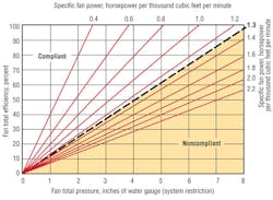
The relationship between the fan-power limitation and fan total efficiency for a single-fan system is shown in Figure 3. Here, fan total efficiency is plotted as a function of fan total pressure. Radial lines extending from the origin are lines of constant SFP. All combinations of fan pressure and efficiency to the left of the 1.3-hp-per-kcfm line comply with the fan-power limitation, while those to the right do not. Systems with low total-pressure requirements can meet the standard with low fan total efficiency.
The SFP limit amounts to an implicit fan-efficiency requirement that is a function of system pressure drop. The 1.3-hp-per-kcfm limit would be higher if pressure-drop adjustments were applicable. For example, a 0.5-in.-wg-pressure-drop credit is given for systems with fully ducted returns. Note that all pressure-drop adjustments allowed by the standard result in an allowable SFP increase satisfied by a 65-percent-efficient fan.
In general, compliance with the fan-power limitation can be achieved with careful system design and existing fan technology. The fan-power limitation is especially easy to meet when system pressure drop is low.
Further energy savings can be realized by requiring fans to meet a minimum energy efficiency—especially when low-efficiency fans can meet the fan-power limitation by a wide margin. However, a requirement based on a single value of minimum fan efficiency can have unintended consequences. Small fans are less efficient than large fans because of a variety of factors, including air-viscosity effects, lack of proportional manufacturing tolerances, and other losses that do not scale with traditional fan laws. Generally, a fan with a 10-in. impeller will have a lower peak efficiency than a geometrically similar fan with a 25-in. impeller.
Setting minimum fan efficiency too high could eliminate smaller fans and the equipment that uses them. However, there now is another option for rating fan energy efficiency.
Fan Efficiency Grade
Fan efficiency grade (FEG) is a new metric recognizing the relationship between impeller diameter and peak total efficiency. FEG is defined by ANSI/AMCA Standard 205 and ISO 12759, Fans -- Efficiency Classification for Fans. FEG is based on peak total efficiency and is an indicator of the aerodynamic quality of a fan. For a given impeller diameter, a fan with a FEG of 85 is capable of greater aerodynamic efficiency than a fan with a FEG of 67, but it does not represent the operating efficiency for a particular application. (A more detailed look at FEG and its integration into Standard 90.1-2013 can be found in an article by Cermak and Ivanovich.3)
The Standard 90.1-2013 fan-efficiency requirement places a minimum FEG of 67 on all fans moving conditioned air, with the exception of fans in certain energy-rated equipment, fans with motors of 5 hp and less, power roof ventilators, and emergency fans. The standard also requires the selection of fans within 15 points of their peak total efficiency. (Note: ANSI/AMCA Standard 205 simply defines FEG and explains how to calculate it. The 15-percentage-point sizing/selection requirement is in a normative appendix.)
A FEG of 67 is considered an acceptable starting point for a new requirement for fans, with revisions likely to bring higher levels and perhaps tighter selection limits. In the meantime, most fans on the market easily can meet the new requirement.
For air-distribution systems with pressure drops greater than approximately 5 in. wg, Standard 90.1 encourages fans with FEGs higher than 67 to meet the fan-power limitation. Table 1 shows several fan selections for a single-fan VAV system without additional pressure-drop adjustments. No additional steps or calculations are required, just a fan with a FEG of 67 or higher and the operating-efficiency condition being met. FEG, operating total efficiency, and peak total efficiency are supplied through a fan manufacturer’s catalog data or selection software.
Examples
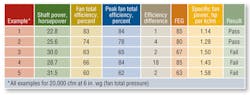
The following examples show the results of selecting a fan based on Standard 90.1 fan-power limits and the new FEG criteria with a 15-percentage-point selection window. In all cases, the fan operating point is 20,000 cfm and 6-in.-wg fan total pressure.
• Example 1: A FEG-85-rated fan operating one point from peak total efficiency is selected. The calculated SFP is 1.14 hp per kcfm; thus, the FEG, fan-power-limitation, and efficiency criterion are met.
• Example 2: The fan is rated at FEG 80 and selected four points from peak efficiency. The calculated SFP is 1.28 hp per kcfm; thus, the FEG, fan-power limitation, and efficiency criterion are met.
• Example 3: The fan is rated at FEG 67 and selected two points from peak efficiency. However, the calculated SFP is 1.50 hp per kcfm, which does not comply with the standard.
• Example 4: The fan is rated at FEG 85, but selected too far (18 points) from peak total efficiency, and the SFP exceeds the limit of 1.3 hp per kcfm.
• Example 5: The fan is rated at FEG 63, which disqualifies it. The selection is close to peak total efficiency (two points), but the SFP is not in compliance.
While these simple examples illustrate the relationship between fan efficiency and fan-power limitation, most practical systems contain multiple fans operating at different conditions. The new efficiency rules will require all applicable fans to have a FEG of at least 67, but the fan-power limitation will continue to encourage high-efficiency fans to offset any low-efficiency fans used in a system.
The 15-point selection criterion is a key component of the new requirement and helps to ensure fans are selected near their peak efficiency.
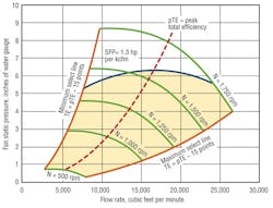
To illustrate the scope of the 15-point selection requirement, a typical operating envelope for a 27-in. double-width-double-inlet airfoil fan with a FEG of 85 is shown in Figure 4. The minimum and maximum system curves correspond to the peak total efficiency less 15. The 15-point restriction is relatively broad and covers a large portion of the fan’s performance envelope. In fact, it is fairly similar to the performance envelope that would be presented by the manufacturer in print catalogs or selection software. Also shown in Figure 4 is a curve indicating the SFP of 1.3 hp per kcfm. For a single fan in a VAV application and in the absence of any pressure adjustments, selections can be made only in the shaded region below the line to meet the current standard. This again stresses the fact the fan-power limitation encourages system designs with low resistance.
Summary
While regulating fans leads to energy savings, much more substantial savings can come from the design and installation of low-pressure-drop systems and the use of high-efficiency fans. Standard 90.1-2013 will encourage good system design and the use of high-efficiency fans to achieve energy goals.
References
1) Westphalen, D., & Koszalinski, S. (1999). Energy consumption characteristics of commercial building HVAC systems volume II: Thermal distribution, auxiliary equipment, and ventilation. Cambridge, MA: Arthur D. Little. Available at http://bit.ly/Westphalen
2) Cermak, J., & Murphy, J. (2011, July). Select fans using fan total pressure to save energy. ASHRAE Journal. Available at http://bit.ly/Cermak_0711
3) Cermak, J., & Ivanovich, M. (2013, April). Fan efficiency requirements for standard 90.1-2013. ASHRAE Journal. Available at http://bit.ly/Cermak_0413
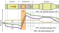
SIDEBAR: Fan Static and Total Pressure
Below, a typical air system driven by a single fan is shown, along with corresponding total, static, and velocity pressures. The total pressure is everywhere, decreasing except at the fan. Total pressure drop represents the energy loss attributed to airflow and is best described by the fan total pressure. This further demonstrates the importance of fan total pressure, rather than fan static pressure, in fan selection.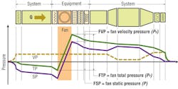
Michael Brendel, PhD, is vice president, engineering and marketing, for Lau Industries, a division of Ruskin Co. He holds bachelor’s and master’s degrees in mechanical engineering from Clemson University and a doctorate in aeronautical engineering from the University of Notre Dame. He has held academic posts at Notre Dame, the Florida Institute of Technology, and the University of Dayton. He later went to work for Valeo developing analytical, computational, and experimental tools. He joined Lau in 2000 to expand the company’s expertise in airflow and acoustic technology. In recent years, he has been active on several Air Movement and Control Association International and ASHRAE technical committees concerning fan technology and fan energy issues.
Did you find this article useful? Send comments and suggestions to Executive Editor Scott Arnold at [email protected].