


Variable-air-volume (VAV) systems with air terminal units have been used extensively in commercial and institutional buildings in the United States for decades. Unfortunately, optimized design of a VAV system with terminal heat is difficult at best because of limitations inherent in VAV and complications posed by design standards and regulations. One new approach involves the pairing of a dedicated outdoor-air system (DOAS) with a variable-refrigerant-flow (VRF) system. By separating the goal of achieving ventilation rates from the goal of maximizing thermal comfort, we can avoid situations in which the two goals are in conflict and efforts suffer from the resulting compromises. What’s more, we can simplify the design process and find system efficiencies that go far beyond those commonly achieved with VAV systems with terminal heating.
Background
In the simplest VAV system, incoming outside air and return air are mixed in a central air-handling unit (AHU) and then pre-heated or pre-cooled. The tempered air is sent by supply-air fan to various occupiable zones at a temperature generally suitable for cooling. In each zone, a terminal unit adjusts airflow based on cooling demand. When a zone requires heating, supply-air flow usually is reduced to a minimum setting and heated, typically via terminal-unit heating coil.
In its simplest form, a DOAS is an AHU dedicated to ventilation, not sized to provide cooling air. DOAS often are supply-only systems with relief to outdoors; however, they also can include exhaust heat recovery. Generally, they are not sized to provide 100 percent air economization (cooling using outside air in lieu of mechanical cooling).
More on DOAS: “Low-Cost Dedicated Outdoor-Air Systems”
More on DOAS: “Optimizing Dedicated Outdoor-Air Systems”
More on DOAS: “Dedicated Outdoor Air, Energy Recovery Rise to School’s Ventilation Challenge”
VRF systems use individual high-efficiency fan coils in interior spaces in combination with high-efficiency condensing units that can serve multiple zones. VRF systems can be arranged to provide energy recovery, moving heat from zones requiring constant cooling to zones that sometimes require heating.
More on VRF: “VRF Zoning Helps School District Achieve Energy- and Cost-Saving Goals"
Limitations of VAV Design
ANSI/ASHRAE Standard 62.1, Ventilation for Acceptable Indoor Air Quality, provides minimum outdoor-air-flow requirements for design conditions. ANSI/ASHRAE/IES Standard 90.1, Energy Standard for Buildings Except Low-Rise Residential Buildings, meanwhile, requires some systems to be operated so ventilation capacity modulates to match ventilation load (i.e., demand). Designing systems to meet both of these requirements is complex.
To help match capacity to load, ANSI/ASHRAE Standard 62.1 allows “dynamic reset,” but leaves the details to the designer. A common approach combines system-level outside-air-damper reset with zone-level demand-control-ventilation (DCV) strategies. For VAV-system energy efficiency to be maximized, the system-level intake/exhaust/relief-damper-reset sequence for space-temperature control and building pressure must be coordinated with an air-economization-reset sequence. Such controls can be quite complex, particularly when pressurization between zones and interaction with exhaust systems also requiring variable-volume control are considered. Weather conditions also can have a major impact on building pressurization and space ventilation.
More on DCV: “Single-Zone, CO2-Based Demand-Controlled Ventilation”
More on DCV: “Multiparameter Demand-Controlled Ventilation"
Other common control sequences for large VAV systems include occupied-hours control, optimal start/stop, fan-pressure reset (“critical terminal unit” control), “ventilation optimization”1 (DCV), ventilation space-temperature setback, supply-air-temperature reset, dynamic space-pressure control, economizer, energy recovery, natural ventilation, and interfaces with building lighting controls, smoke detection, fire alarms, and even security systems. Interplay between these control schemes vastly complicates efforts to optimize building energy use.
Further complicating VAV-system design is the need to follow the ANSI/ASHRAE Standard 62.1 ventilation-rate procedure, which asks designers to use the multiple-space equation (MSE) to calculate the “critical” zone, the space driving the overall (system-level) outside-air fraction. Zone-level flows then are changed to meet zone-level requirements. Once the critical zone has been chosen, heating-turndown requirements push designers to overventilate some zones by increasing heating minimum settings. This typically changes the critical zone and reduces the overall outside-air fraction at the central-system level, substantially affecting AHU components.
To respond to changes in zone population, dynamic reset of VAV systems, combining zone-level DCV with system-level ventilation reset, often is applied. Ventilation reset is a control scheme by which the MSE is solved dynamically to change system outside-air setpoint. This often is applied with airflow-measuring stations, along with electronics and software to control dampers based on relative airflow, at the central system.
Central-system design usually is based on the static-condition (design) critical zone, while in the real world, zone population varies dynamically along with building HVAC load (internal and weather-related) over the course of a day. Maximizing energy efficiency under these conditions pushes the envelope in terms of building-system design and building-operation hardware and software. Some commercial software packages can aid ventilation reset, calculating critical ventilation zone per ANSI/ASHRAE Standard 62.1. Calculating minimum system outside air, however, usually requires the overriding of some terminal-unit turndowns, which changes the critical zone. This is allowed by ANSI/ASHRAE/IES Standard 90.1 because only a few zone overrides can change a system outside-air setting by many percentage points, saving considerable pre-treatment energy and reducing central-system size. Meanwhile, inputs to these calculations vary with system load, which also can change the critical zone. At the same time, other overrides, such as of supply airflow for makeup to areas with exhaust flows exceeding ASHRAE minimum rates, are necessary. These overrides and simultaneous variations result in the need for iterative calculations involving all environmental variables; such calculations currently are beyond the scope of commercially available software.
Zoning is another limitation. History shows building-construction economics can drive VAV-system designers to combine up to several rooms on a single ventilation and temperature-control zone. Because heating and cooling loads can vary widely between rooms on a single zone, this often leads to discomfort in certain rooms when other rooms on the same zone are not at the design load.
In summary, designing a VAV multizone HVAC system can be challenging to say the least. Overlaying the various requirements, exceptions, and system functions results in iterative design simulations that must be re-run whenever a room’s size changes. Complying with all codes while addressing the competing interests of ventilation and energy optimization is theoretically possible,2 and technical solutions partly exist and are being developed. But in practice, designing and redesigning systems with complex, iterative calculations is not very practical, and manual overrides generally do not fully optimize system designs. Meanwhile, designers often estimate “block” (net) load based on building-envelope heating and cooling, considering neither variations in internal and ventilation heating/cooling loads nor airflows needed for ventilation and space pressure control, significantly undersizing or oversizing systems as a result.
Limitations of VAV-System Installation and Operation
In decades past, the basis of widespread use of VAV systems was their inherent high air-change rate, maintained during reheat. Now, standards push the minimization of reheat and air-change rates for the sake of energy conservation.
VAV systems require extensive space for ducts for distribution of low-pressure air downstream of terminal units. This is particularly troublesome when interleaving return-air ducts, exhaust-air ducts, supply-air ducts, terminal units, light fixtures, conduits, cable trays, and structure in ceiling space while still allowing room for maintenance. Meanwhile, terminal units themselves can require considerable physical space. With codes prescribing use of bigger ducts and coils to reduce air-pressure losses, available space is shrinking.
Ceiling-space concerns are exacerbated by air-economizer requirements. Central VAV systems usually have air-economizer dampers as needed to meet ASHRAE standards. With an air economizer, supply and return ducts must be sized to accommodate use of outside air for cooling when conditions are right.
VAV central fans are selected based on their flow characteristics. Fan curves generally demonstrate static efficiency has diminishing returns at some fraction of design fan speed. This “maximum turndown” concept typically is used for selecting fans for best static efficiency at design conditions, but also helps to illustrate the problematic nature of maximizing efficiency in VAV systems under dynamic conditions. If fan efficiency is not considered at maximum turndown (minimum speed), it is not being balanced against all other system efficiency effects.
Centralized supply fans can be quite large and, thus, are likely to generate noise and vibration. Systems for abating this noise and vibration can be costly. Also, large fans require large seismic restraints and a relatively beefy structure for attaching those restraints. Repair, replacement, and modification of large central fans in VAV systems can require long lead times for custom equipment and to accommodate construction impacts, such as the removal of structure for access to large fan components.
Economizer dampers in central systems are affected by pressure losses. At the same time, maximizing the energy effectiveness of a VAV system requires consideration of economizer cooling in real time, a formidable challenge when laying economizer control over other pressure controls. In short, the best-designed economizer-damper controls can be quite complex, and these dampers and controls often are not well-maintained and, thus, can have a high rate of failure.3
VAV systems have other inherent pressure losses that constantly consume fan horsepower. These include terminal-unit dampers, reheat coils, sound traps, and restrictive fittings in medium-pressure ducts.
VAV systems require intensive iterative technical balancing of heating-water, cooling-water, and air flows. This balancing can be costly and time-consuming, involving multiple design disciplines and building trades.
Automated control of complex VAV systems is intricate, involving indoor/outdoor space pressurization, individual space pressures, relative pressure losses through ducts/dampers/diffusers/louvers, multiple overlapping dynamic resets (airside and waterside), signal-select routines for combined zones, complex terminal-unit cooling/turndown/reheat schemes, heat-recovery control, defrosts, equipment start/stop, DCV, fire- and life-safety routines, lighting-control interfaces, and time-clock functions. Built-up VAV systems tend to demand combination and optimization of these functions, while DOAS and VRF systems tend to deal with them separately, which can simplify a building-automation system by an order of magnitude.
Energy-recovery components in built-up VAV systems tend to have relatively high airflow losses because of the economic pressure to contain the size of VAV air handlers. Also, these energy-recovery systems can be complex, involving bypass dampers, sometimes controls and additional maintenance for heat wheels or other energy-recovery devices, and pressure losses and controllability issues related to added dampers, coils, pumps, and piping.

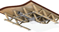
Supply-air diffusers typically found in VAV systems are static, meaning their function changes when terminal units reduce airflow. This is especially problematic with VAV heating turndown because air is not thrown as far into the room (Figure 1), sometimes leading to space-temperature stratification. Also, VAV room air throttling creates noise that can be particularly troublesome in office and educational institutions. Larger and more expensive equipment, as well as components such as duct liner and silencers, can be required, adding to capital and operating costs.
Other Drawbacks of the VAV-System Paradigm
When mixed air is being cooled at an AHU and terminal supply air is being heated, some degree of “reheat” can occur, resulting in less-than-optimal energy efficiency.
Particularly high energy penalties can be paid where reheat occurs, which often is zones with high ventilation requirements and low or intermittent cooling loads. For example, a typical conference room has variable occupancy, a high maximum occupancy density, and low unoccupied cooling requirements. In such a zone, delivery of minimum ventilation air that has been mechanically cooled at an AHU will cause subcooling, necessitating reheat. If the reheat is limited, then when additional occupants enter the room, there may be a thermal lag, a delay in the cooled space-temperature sensor detecting the increase in occupancy. This will delay the signaling of the terminal unit to change from its minimum setting and cause ventilation deficiencies.
There are many buildings in which initial operating conditions have been overridden for any number of reasons and not yet restored. Some consulting firms and organizations emphasize the need for retrocommissioning in these cases. Another option is to increase how “self aware” buildings are in terms of not only energy consumption, but ventilation performance, moisture-management performance, and even pressure-relationship management.
In the area of ventilation performance, accuracy is critical. This applies not only to control routines, but the data on which they rely. If monitoring data for, say, carbon dioxide (CO2) is sloppy and inaccurate, how can control-procedure modifications be any different?
Historically, the primary driver of the use of VAV systems has been energy savings. In theory, fan energy is saved by slowing a system fan; in practice, at low speeds, reduced system-level airflow can make achieving code-required ventilation at all zones difficult, despite reductions in the amount of supply air provided. At the same time, large fans and associated variable-speed drives have limited turndown, so commanding a fan to slow further may not produce expected energy savings.
Recommendations
A lot of buildings have and will continue to have VAV systems. Thus, there is a continuing need to improve VAV-system operation and reduce risk and uncertainty in the delivery of ventilation. Several approaches are available.
Techniques for increasing mechanical advantage include selecting more mechanically efficient fans and using premium-efficiency motors with improved variable-frequency drives. Another approach is to use a direct-drive fan array for improved airflow turndown and accuracy.
Additionally, we can provide control routines that coordinate VAV terminal-unit airflows with occupancy schedules and occupancy sensors to ensure optimal start for room flush, similar to “morning warmup” routines.
Another approach is to heighten building self-awareness with respect to ventilation performance. Fortunately, intelligent monitoring systems designed to help make buildings aware not only of ventilation, but temperature, moisture management, and pressure relationships across building zones and even filters in AHU are in development.
Smart building controls require additional sensing of temperature, pressure, and occupancy. For example, airflow sensors with control routines that coordinate outside-air flow with other requirements, such as cooling, space pressure, and dynamic changes in economizer operation, can be provided in outside-air intakes to maintain pressure relationships and meet airflow requirements. Of course, the amount of outside air entering a HVAC system can be useful to know, but it indicates nothing about how the air is distributed and how that relates to the distribution of people. A far smarter approach, fostered by the U.S. Green Building Council (USGBC) in its LEED (Leadership in Energy & Environmental Design) green-building rating systems and ASHRAE, is to implement accurate CO2 monitoring in spaces with the highest occupancy to assess the amount of ventilation being provided. A goal of smart building controls should be to monitor ventilation performance in enough spaces to determine how well outside air is reaching the breathing zone of all spaces (as opposed to knowing merely how much outside air is entering the HVAC system and how much is provided in conference rooms).
VAV terminal units often are linked to occupancy sensors through control routines. What this approach lacks is a feedback loop indicating whether additional ventilation is being provided upon occupancy. Just generating a signal that occupancy has occurred is not a fail-safe solution, as there still needs to be programming to interpret the signal and instruct the HVAC system to modify its performance. What’s more, the HVAC system needs to be optimized to be able to modify ventilation performance.
Smart building controls and building intelligence in general should go beyond the mere sending of signals to assessing whether desired operational details are being implemented. A truly smart building needs to include diagnostic feedback on “end point” performance as part of its ongoing commissioning capabilities. In other words, it needs to go beyond merely asking whether a signal was generated to determining whether an appropriate amount of ventilation is being provided as occupancy varies. ASHRAE’s and the USGBC’s impetus to provide DCV (often measured with a few local CO2 sensors) is a beginning, but more needs to be done.
An aspect of controls frequently overlooked is the quality of sensing data. If buildings are to achieve autonomics, by which controls are aware of key performance parameters, either sensors need to become significantly more accurate or we need to develop ways to collect more high-quality data.
In general, the industry needs to expend the extra effort to develop VAV-system controls that not only provide sufficient accurate data, but optimize tradeoffs between all HVAC operating functions. Such controls are being considered and partly developed.
Fortunately, a design paradigm is emerging to compete with the old VAV model. This new model can reward us with simplified system design, while letting us achieve the increased system efficiencies that energy costs are demanding. Next month’s article will review the DOAS/VRF design paradigm in depth.
References
1) Stanke, D., & Bradley, B. (1998, January). The threefold challenge of …ventilating single-duct vav systems. Trane Engineers Newsletter. Available at https://www.trane.com/commercial/uploads/pdf/673/en27_01a.pdf
2) Murphy, J. (2011, October). High-performance vav systems. ASHRAE Journal, pp. 18-28.
3) WHPA. (2013, March). Economizer experts gather to solve the problem. Retrieved from http://performancealliance.org/Newsletters/March2013/tabid/348/Default.aspx
Grant Bowers, PE, LEED AP, is a mechanical engineer with SSOE Group, provider of architecture, engineering, construction-management, and specialized services worldwide. Over the last 20-plus years, he has developed expertise in the design of mechanical systems and management of mechanical design and construction projects for manufacturing, cleanroom, laboratory, office, government, medical, and education facilities. He can be contacted at 503-439-8777 or [email protected].
Did you find this article useful? Send comments and suggestions to Executive Editor Scott Arnold at [email protected].