Optimizing the Energy Efficiency of Desiccant Dehumidifiers
Condensation on a cooling coil generally is considered the most energy-efficient method of dehumidifying air, as long as performance requirements fall within the practical range of refrigeration. For HVAC systems designed for conditioned-space temperatures of 65°F or higher, the lower end of this range is 32°F dew-point humidity—in theory; in practice, it is more like 40°F to 45°F dew-point humidity. Allowing for space-envelope, occupant, and process moisture load, the practical lower limit for refrigeration-based humidity control is about 45-percent RH at typical ambient comfort temperature.
Many institutional and industrial applications require conditioned space to be maintained below 45°F dew-point humidity. A few examples are hospital surgical suites, pharmaceutical manufacturing, and a variety of food-processing applications. When the dew-point humidity required in a space is 45°F or less, desiccant-dehumidification equipment in combination with refrigeration commonly is used for humidity and temperature control.
There are two basic types of desiccant dehumidifiers: liquid and solid. This article will focus on solid-desiccant equipment.
Basics
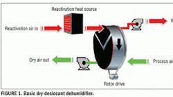
Figure 1 shows the basic elements of a solid-desiccant dehumidifier. The heart of a solid-desiccant dehumidifier is the desiccant rotor (or wheel), which consists of a large number of small passages running parallel through the depth of the wheel. The walls of the passages contain—in a high percentage by weight—a solid desiccant, such as silica gel. The cabinet housing the wheel is divided into two or more sectors equipped with baffles and air seals, which allows two or more air streams to pass through the wheel without mixing. The wheel is rotated slowly through the sectors so that it is alternately exposed to the separate air streams. Air to be dehumidified is passed through the larger sector (usually called the process sector), and moisture is adsorbed by the desiccant. Heat, then, is transferred to the dehumidified air, which leaves the wheel drier and warmer than when it entered. Eventually, the desiccant becomes loaded with moisture and is exposed to a second air stream as the wheel rotates. The second (reactivation) air stream is heated; it heats the desiccant and supplies enough heat to evaporate the moisture. The moisture is carried away by the reactivation air, which leaves the wheel wetter and cooler than when it entered. The dried wheel rotates into the process sector to repeat the cycle.
Desiccant dehumidification in combination with refrigeration generally is a more energy-efficient and practical method of producing low-humidity air than refrigeration alone. However, it still is an energy-intensive process; the cooler and drier the process air, the more energy is required, regardless of which process is used. If a desiccant dehumidifier is operated continuously and delivering fairly dry air, it is not unusual for annual operating cost to exceed the purchase price of the dehumidifier. This highlights the importance of making the desiccant-dehumidification process as energy-efficient as practical.
Purge Arrangements
To improve the thermal efficiency of the dehumidification process, several "purge" arrangements are used.
One arrangement is a closed-loop purge (Figure 2). The basic concept is to recycle reactivation heat from the reactivation discharge to the reactivation inlet. This reduces both process-cooling and reactivation-heating requirements. At least two manufacturers offer this arrangement as an option, depending on the specifics of the application.
Another approach is to use a single purge sector to cool the media between the reactivation and process sectors and use the heated air for part or all of the reactivation-air stream. This cools the wheel entering the process sector, improving its dehumidification performance. A simple version of this is shown in Figure 3, but several variations exist.
Part-Load Energy Requirements
In most applications, dehumidification load varies, depending on weather conditions and activities occurring in the conditioned space. A percentage of the air entering a desiccant dehumidifier typically is outside makeup air needed for pressurization and ventilation of the conditioned space. Other portions of the dehumidification load are attributed to humid air from the surroundings leaking into the conditioned space and variations in the activities occurring within the conditioned space. As a consequence, most desiccant dehumidifiers operate at full load only a small percentage of the time over the course of a year. Most of the time, they operate at a relatively small percentage of their design load—frequently, less than 50 percent.
Extensive modeling was performed for a number of locations representative of regional climates in North America. The objective was to compare the annual energy use of a dehumidifier using a "standard" control arrangement and one using an optimized control strategy for reactivation airflow, reactivation temperature, wheel rotational speed, and process airflow through the wheel. Figures 4 and 5 show the results of a test case involving a space continuously maintained at 72°F, 30-percent RH with 10-percent precooled outside/pressurization air, and a 50-percent fluctuation in moisture load on the dehumidifier. Figures 4 and 5 show a relationship between climate and energy savings. Taking the extremes of the test case into account, annual energy savings range from less than 10 percent in Miami (subtropical climate) to over 60 percent in southwestern Canada (dry climate).
For the example case, annual energy savings for a dehumidifier handling 10,000 cfm are in the range of $5,000 to $20,000 a year, using typical utility costs in North America.
The savings shown are for a basic dehumidifier without purge sectors. The same control strategy can be applied to units with purge sectors, but the savings will be somewhat less because the units are more energy-efficient to begin with.
Bill Griffiths has more than 40 years of experience in the design and application of desiccant-dehumidification equipment, primarily for industrial and institutional uses. Currently, he serves as a consultant for desiccant-equipment manufacturers and end users.
Did you find this article useful? Send comments and suggestions to [email protected].
