Blue Devils Go Green: Duke Converts Steam Plant From Coal to Gas
In April, Duke University in Durham, N.C., celebrated success of the athletic kind, winning its fifth NCAA Division I men’s basketball tournament. Just a short walk from the team’s home, Cameron Indoor Stadium, and Head Coach Mike Krzyzewski’s office, the Blue Devils are celebrating success of the environmental kind, with the $35 million restoration and conversion from coal to natural gas of the West Campus Steam Plant.
Built in 1928, the plant provides steam for space and process heating to more than 7 million sq ft of facilities, including critical research and medical facilities, year-round. The plant contains six boilers and can produce up to 420,000 lb of steam per hour at 150 psig. Prior to the renovation, which involved the replacement of aging coal-fired boilers with modern gas-oil-fired units and major upgrades to all site and plant systems, the plant burned more than 50,000 tons of coal a year.
Reducing Site Footprint
The West Campus Steam Plant was built to provide heating for the original quad. While the quad was located in the heart of campus, the plant was constructed on the outskirts, in the middle of a wooded area. The ensuing years saw buildings encroach the once isolated plant on all sides.
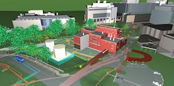
With the demolition of baghouses, ash silos, and lime silos and the removal of the coal pile, the 33,000-sq-ft site was reduced by more than 30 percent (Photo A). Parking areas were laid out with improved fuel and delivery-truck access, and central electric generators, along with fuel-oil-storage areas, were integrated into the site. Infrastructure systems, including direct-buried chilled-water, steam, and medium-voltage-power systems, were consolidated into utility corridors and replaced. Engineers used AutoCAD Civil 3D design and documentation software from Autodesk Inc. to model the site, which allowed them to efficiently route utilities and avoid conflicts underground (Photo B).
Improving Building Functionality
Engineers performed an in-depth assessment to determine the structure’s condition and adequacy for repurposed loading.
Prior to the renovation, much of the structure of the West Campus Steam Plant was hidden by ductwork, equipment, and piping slated for replacement. This led to the need for assessment of the structure during construction. After large exhaust ductwork was removed, brick and steel of the north façade was found to be in poor condition. Selective demolition of exposed encased steel members, which showed signs of cracking, was completed. The team determined that on the main level the steel required only minimal remediation, including the removal of minor rust and the application of rust-inhibiting paint, while on the upper clerestory level full replacement of the steel and the building of an internal frame to support the roof was necessary.
Building circulation and wayfinding were upgraded with new mezzanine connections, additional stair towers, larger doorways, and multiple roof-access points. The plant-operations team was heavily involved to determine the most ideal pathways and required service aisles for maintenance of each piece of equipment.
With the university wanting to incorporate learning and touring functionality in the circulation plan (the plant-operations team regularly leads facility tours for engineering students and organizations), the steam-header mezzanine was built with a balcony overlooking the boilers and custom heat-recovery unit.
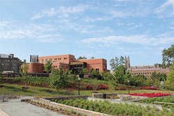
With the construction of medical buildings and the addition of a pedestrian esplanade near the steam plant, modifications to the plant’s appearance were deemed necessary for aesthetic reasons (Photo C). After much discussion, the structural and architectural team restored the plant’s façade to its original 1920s look, but with a few modern touches. Modifications included a brick façade, new windows, and additions to house new deaerators and a lobby area.
Innovative and Reliable Solutions
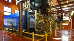
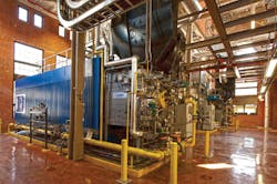
A unique energy-saving feature of the West Campus Steam Plant is the custom flue-gas heat-recovery system (HRS). The HRS uses energy from stack gas to boost condensate return temperature and preheat makeup water upstream of its entry point at the deaerator. It features two non-condensing heat exchangers, one fully condensing stainless-steel module, and its own supply fan. Plant energy savings and extra unfired capacity during summer is 4,000 MBH, while winter recovery rates can climb to more than 10,000 MBH. Boosted by energy recovery and near-year-round base-load hours, new Boiler 1’s and new Boiler 2’s annual fuel-to-steam efficiencies are expected to be nearly 90 percent (Photo D).
Other exceptional mechanical features include a combined steam header with three distinct distribution paths to campus, redundant deaerators, condensate and fuel-polishing systems, and a new hybrid programmable-logic-controller and supervisory-control-and-data-acquisition system. Piping was organized in a vertical hierarchy structure with custom supports. Mechanical equipment generally was designed in pairs for best alignment with the plant’s electrical strategy.
Built for reliability, the all-new electrical system features two incoming services, redundant transformers, dual-ended switchgear, and Bus A and Bus B panel configuration. One unique aspect of the electrical system involves the coal-bunker area, which was repurposed to house medium-voltage and emergency power switchgear. A new 3-MW diesel generator was custom-designed to provide backup power for the plant and to centrally distribute power to nearby buildings. Another interesting feature of the system is an exterior stack cap lantern with fully programmable light-emitting-diode (LED) lighting system programmed to glow “Duke Blue” (Photo E).
‘Renovating an Airplane in Flight’
Comparing the process to the act of renovating an airplane in flight, the design, operations, and construction team implemented all conceivable phasing and sequencing techniques to maintain plant steam output during construction. The project was divided into three distinct document packages, and major equipment was pre-purchased. Temporary boilers were utilized for primary and backup capacity for a substantial portion of the construction process. Given that all of the plant’s piping systems were replaced, transition plans were made for each subsystem, such as steam, feedwater, and compressed air. Planning analysis involved careful reference to the 3D building information model so any conflicts between existing and replacement piping could be identified.
A multistep plan that included the addition of pipe taps and temporary cross connections was developed. After the operations and construction team provided input, the plan was updated and ready for implementation. During rare full plant outages, a sequenced hour-by-hour plan with work breakdown structure was developed to facilitate on-time completion of tasks and identify any pinch points.
The project was completed in July 2014. The project team included Duke University; RMF Engineering Inc., which handled mechanical, electrical, plumbing, civil, and structural design; Flad Architects, which handled architectural design; Surface 678, which handled landscape design; and Lend Lease, which served as construction manager. The project was awarded LEED Silver status by the U.S. Green Building Council, received the Award of Merit for Renovation/Restoration in Engineering News-Record’s Southeast 2014 Best Project Awards competition, and received an Excellence in Construction Merit Award from the Carolinas chapter of Associated Builders and Contractors.
Greg Carnathan, PE, CEM, LEED AP, is a mechanical engineer and associate with RMF Engineering Inc., a firm specializing in district-energy-system planning, design, and commissioning. His responsibilities include project management, master planning, energy analysis, and design. He can be contacted at [email protected]. Cheryl Piner, PE, is a project manager with RMF. She specializes in structural design for utility-plant renovations and civil design for thermal utility distribution systems. She can be contacted at [email protected].
Did you find this article useful? Send comments and suggestions to Executive Editor Scott Arnold at [email protected].


