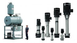
A steam boiler is a pressurized tank; for catastrophic failure and loss of life to be avoided, it must always have the correct amount of water. For this and other reasons, the feedwater pump has to be sized for a flow that is a certain percentage higher than what the boiler requires for normal operation.
It also is important to be cognizant of the vented-receiver or deaerator water temperature and the presence of treatment chemicals, both of which can have an impact on materials of the pump and mechanical seal.
Steam-boiler systems are available in a broad range of sizes. The following steps apply to pump selection for an industrial steam boiler with a horsepower range of 100 to 1,200 and a design pressure of 150 to 500 psig.
With large applications, it is common to install multiple boilers parallel to one another. There are two common feedwater-pumping-system designs for this:
- Direct feed. This type of system is common because it is easy to maintain and switching out a complete boiler or feed pump is simple.
- Booster sets. Instead of individual feed pumps supplying boilers, there is a booster set supplying a common manifold, from which water moves to individual boilers through a modulating feedwater valve.
Following are 16 steps for determining the proper boiler feedwater pump for a system:
1. Determine the control method to be used. Check the specification.
2. Calculate the base flow rate. Base flow rate is found using the formula:
boiler maximum-capacity horsepower × 0.069 × C
Use the boiler maximum-capacity horsepower from the boiler manufacturer’s specification. The number 0.069 is a constant. The “C” value varies depending on whether the pump will cycle on and off in intermittent operating mode (C = 1.50) or operate in a continuous feed mode (C = 1.15).
3. Add for continuous boiler blowdown flow. This step is not always required and not always specified. When needed, it often is about 10 percent of the pump’s best-efficiency-point flow rate, but it can vary and is set by the water-treatment company. This continuous blowdown flow is intended to remove total dissolved solids from boiler water and is not to be confused with the bottom blowdown of boiler water.
4. Add for bypass flow, if required. Some control methods use a flow bypass recirculation line and a feed valve. The bypass flow ensures a minimum amount of flow passes through the pump to avoid operation at close to shutoff head. The bypass recirculation flow must be sized based on the pump manufacturer’s minimum flow requirement for each pump. The amount of flow will vary, but often is based on about 10 to 20 percent of the pump’s nominal flow rate at the best efficiency point.
5. Determine the total flow rate required. Calculate the sum of the base flow, bypass flow, and continuous blowdown flow, if required.
6. Calculate base head for the feed pump. When calculating total dynamic head for all centrifugal pumps, consider all of the influencing factors on both the suction side and the discharge side of the pump. Use the following formula:
base head in feet = maximum boiler operating pressure × 2.31 × 1.03 ÷ liquid specific gravity
7. Add all suction-piping head components. Calculate the gauge pressure in the deaerator tank, the elevation head from the tank’s waterline on the suction side to the pump’s lowest impeller, and all suction-line friction losses.
8. Add all discharge-piping-system head components (including feed valve, if required). Determine all friction losses on the discharge side of the pump, plus the elevation to the boiler’s feedwater inlet relative to the pump’s discharge.
9. Determine the total pumping head. Calculate the sum of all head components, including the base head with safety factor, suction-side piping-system head, and discharge-side piping-system head.
10. Calculate head at the boiler-safety-valve setting plus 3 percent. In addition to achieving the correct head at the required flow rate, the pump must be capable of achieving a shutoff head (the head at zero flow) 3 percent above the boiler-safety-valve setting. For example, if boiler operating pressure is 130 psi, convert to feet of head by multiplying by 2.31, then multiply by 1.03 for the overage, and then divide by the liquid’s specific gravity.
11. Determine the boiler’s feed-tank water temperature.
12. Calculate the net positive suction head available (NPSHa). The formula is:
absolute pressure in feedwater tank ± elevation of minimum water level in tank above feed pump − vapor pressure of water in feed tank − suction-line friction loss
13. Make preliminary pump selection. Review the curves available to ensure the pump meets these conditions.
14. Ensure the shutoff head is 3 percent or more above the safety-valve setting.
15. Check net positive suction head required (NPSHr) vs. NPSHa. This calculation must be performed for every installation because no two are exactly alike.
16. Ensure material compatibility. Check both chemical and temperature compatibility.
After these steps are completed, the final pump selection can be made.
To view a three-part educational series on boiler-room pumping systems, go to www.cleaverbrooks.com/webinars.
Steve Connor is an expert on steam and hot-water generation. He can be contacted at [email protected]. Jim Swetye is a senior technical trainer for Grundfos Pumps. He can be contacted at [email protected].
Did you find this article useful? Send comments and suggestions to Executive Editor Scott Arnold at [email protected].


