Unlike other building systems, it is virtually impossible to test an atrium smoke-control system to design conditions. This primarily is because design conditions involve large design fires that can damage an atrium. Design conditions also can include wind, for which systems are nearly impossible to test. It is essential that an atrium smoke-control system be designed properly and tested to verify it operates as intended and that system components be inspected to ensure they function as specified.
This article discusses atria smoke-control methods for a variety of large open spaces, such as enclosed shopping malls, arcades, sports arenas, exhibition halls, and airplane hangers.
Smoke-control technology has made significant advances in recent years. Design analysis of these systems commonly is accomplished via one or more techniques, such as algebraic equations and zone-fire and computational-fluid-dynamics (CFD) modeling.1 A detailed mathematical treatment of these techniques is beyond the scope of this article; however, state-of-the-art atrium smoke-control technology is addressed.
BASIC CONCEPTS
When a fire occurs, smoke rises in a plume. As the plume rises, it pulls air from the surrounding space, which causes the plume's mass flow to increase and its temperature to decrease. When the plume reaches the ceiling, it spreads out, forming a layer. An atrium smoke-control system exhausts smoke from that layer, providing a relatively smoke-free environment (figures 1 and 2).
Plume dynamics have been studied extensively, and algebraic equations have been developed to calculate the mass flow and temperature of a plume based on plume height and fire size. For steady-state conditions, exhausted smoke equals the mass flowing from a plume into a smoke layer. Thus, equations can be used to calculate the temperature and flow rate of smoke exhaust.
A book recently published by the International Code Council (ICC)2 focuses on the requirements of the 2006 International Building Code (IBC),3 including the equations needed for system analysis. Intended for smoke-control designers and code officials, the book addresses all aspects of smoke control, including pressurization systems; atrium, stairwell, and elevator smoke control; design fires; smoke-control equipment; and inspection and commissioning. The book also details the 2006 IBC's adoption of National Fire Protection Association (NFPA) 92B: Standard for Smoke Management Systems in Malls, Atria, and Large Areas.4 A book on smoke control published by the American Society of Heating, Refrigerating and Air-Conditioning Engineers (ASHRAE)5 includes derivations of many of the equations used in smoke-control design.
The algebraic-equation approach is based on an idealization in which a smoke layer's temperature is the same throughout and the bottom of the smoke layer is a horizontal plane, called the smoke-layer interface. In this idealization, “smoke-free” air is present 0.001 in. below the interface. During a real fire, a transition zone actually exists between the smoke layer and the air below. However, the algebraic-equation approach is useful for smoke-control design.
Smoke filling, an alternative approach to smoke exhaust, requires that occupants evacuate from or through the atrium as smoke fills the space. Smoke filling applies only to atria that have very large volumes above their highest walking surfaces, which create filling times that are sufficient for evacuation, including the amount of time occupants need to become aware of a fire and prepare for movement to an exit. Smoke-control equipment is not required for smoke filling.
Smoke-filling time can be calculated via algebraic equations and CFD and zone-fire models. Filling-time algebraic equations can be found in the previously mentioned book published by the ICC.2 Over the last three decades, many zone-fire models have been developed, the most sophisticated of which is Consolidated Model of Fire and Smoke Transport (CFAST), developed by the National Institute of Standards and Technology (NIST).6 CFAST is available for free at http://fast.nist.gov. CFD modeling is addressed later in this article.
Because few atria are large enough to rely on smoke filling, the remainder of this article deals only with atrium smoke-exhaust systems.
MINIMUM DESIGN SMOKE-LAYER DEPTH
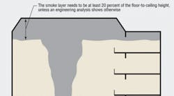
It is important that sufficient space be available for a smoke layer to form. When a smoke plume reaches the ceiling, smoke flows away from the point of impact in a radial direction, forming a “ceiling jet.” When the ceiling jet reaches a wall, smoke flows around and under the ceiling jet. The ceiling jet and the smoke flow under the ceiling jet each have a depth of about 10 percent of the floor-to-ceiling height, meaning that the normal minimum smoke-layer depth is about 20 percent of the floor-to-ceiling height. The smoke layer needs to be at least this deep, unless an engineering analysis shows otherwise (figures 1 and 2). Such an analysis can be based on full-scale or scale-model fire tests or CFD modeling.
SMOKE PLUMES
There are many kinds of smoke plumes, but axisymmetric plumes and balcony spill plumes are most commonly considered during smoke-control design.
An axisymmetric plume is expected to accompany a fire that originates on the floor of an atrium away from walls (Figure 1). In this case, air is entrained into the plume from all sides and along the entire height of the plume. The mass rate of an axisymmetric plume depends on the size of the fire and the distance from the base of the fuel to the smoke-layer interface.
A balcony spill plume flows under and around a balcony before rising. Air is entrained into the plume as the plume flows under and around the balcony and smoke rises above the balcony (Figure 2). The mass rate of a balcony spill plume depends on the size of the fire, the dimensions of the balcony, and the distance from the balcony edge to the smoke-layer interface.
A window plume comes from a room that has a fully developed fire. Because a fully developed fire is not expected with a properly functioning sprinkler system, window plumes are considered only for very unusual applications.
MAKEUP AIR
Makeup air can be provided by fans or openings to the outside. Makeup air must be provided for exhaust fans to operate at design flow rates. Makeup-air supply points should be below the smoke-layer interface. When makeup air is provided via openings to the outside, the effect of wind on the makeup-air openings should be analyzed.
Large openings and small paths are used to provide makeup air via openings to the outside. Large openings include open doors, windows, vents, etc. Small paths include construction cracks and gaps around closed doors and windows.
Makeup air for fan-powered/mechanical smoke-exhaust systems should be less than the mass flow rate — approximately 85 to 95 percent — of exhaust. The remaining 5 to 15 percent of the air will enter the large-volume space via small paths. Supplying less than 100-percent makeup air avoids positively pressurizing a large-volume space.
Unless a higher velocity is supported by engineering analysis, makeup air should not exceed 200 fpm in areas in which it could come into contact with a smoke plume. This limit prevents significant deflection of the plume and disruption of the smoke layer (Figure 3). This type of engineering analysis could be based on comparisons developed with full-scale, scale, or CFD modeling.
SMOKE STRATIFICATION
The result of rooftop solar radiation, a hot layer of air often forms under an atrium's ceiling. The temperature of this layer often exceeds 120°F. As previously mentioned, plume temperature decreases as plume height increases. For a 1,800-Btu-per-second fire in an atrium with a floor-to-ceiling height of 60 ft, the ceiling-smoke temperature would be only about 95°F.
When a plume's average temperature is less than a hot-air layer's, smoke will stratify under the hot-air layer, preventing smoke from reaching ceiling-mounted smoke detectors. Projected-beam smoke detectors should be used for applications in which smoke stratification is possible. Three commonly accepted arrangements of projected-beam smoke detectors can be used for atrium smoke control: upward beams that detect the smoke layer, horizontal beams that detect the smoke layer at various levels, and horizontal beams that detect the smoke plume. For these arrangements, the spacing of detectors is critical. Spacing recommendations can be found in the previously mentioned book published by the ICC.°
DESIGN FIRES
Design fires, which can be deemed steady or unsteady, have a major impact on an atrium smoke-control system. Design-fire size is expressed in terms of heat-release rate. Typically ranging from 1,800 to 8,000 Btu per second, design fires should be evaluated as part of a smoke-control system's engineering analysis. For a discussion of the concepts behind design fires, see the HPAC Engineering article “Design Fires: What You Need to Know”7 and the conference paper “Determining Design Fires for Design-Level and Extreme Events.”8 A detailed treatment of design fires can be found in the previously mentioned book published by the ICC.2
Designers should not make the blunder of thinking that an atrium with almost no materials should have a very small design fire. This kind of thinking does not account for changes in space use or transient fuels. Transient fuels are materials that reside in a space temporarily, such as holiday decorations, paint and solvents used for redecorating, cardboard boxes awaiting removal, and upholstered furniture. Transient fuels must not be overlooked when analyzing design-fire size.
PLUGHOLING
Plugholing occurs when air below is pulled through a smoke layer and into smoke exhaust (Figure 4). Plugholing lowers the smoke-layer interface and can expose people to smoke. Lowering the interface can result in system failure; however, plugholing can be prevented by keeping flow relatively low at each smoke-exhaust inlet. To avoid plugholing, the maximum flow rate at smoke-exhaust inlets must be calculated correctly and the number of inlets chosen carefully.
CFD MODELING
CFD modeling divides a space into a large number of cells and solves the governing equations for each. (Governing equations are nonlinear, partial differential equations for conservation of mass, momentum, and energy.) Atrium applications can have 100,000 to 1 million cells. Obstructions, such as walls, balconies, and stairs, should be considered. Boundary conditions, including smoke exhaust and makeup air, should be defined.
Atrium smoke-control designs based on the conventional algebraic-equation approach tend to be conservative and have exhaust flow rates that are somewhat high. Conversely, CFD modeling can be the basis for exceptions for the requirements to smoke-layer depth, the 200-fpm limitation on makeup air, and plugholing.
CFD modeling provides a high degree of confidence that a tenable environment will be preserved. CFD modeling's strength is that it can simulate fire-induced smoke flows, which algebraic equations cannot.
There are some good general-purpose CFD models, but the NIST's Fire Dynamics Simulator (FDS)9 is for fire applications. While the annual fee to use a commercial CFD model can be tens of thousands of dollars, the FDS and its associated documents can be downloaded for free at www.fire.nist.gov/fds/downloads.html. For a non-mathematical discussion of CFD modeling, see the previously mentioned HPAC Engineering article. The previously mentioned book published by the ICC includes a detailed introduction to CFD modeling.3
REFERENCES
-
Klote, J.H. (2006, June). CFD: A new way to design atrium smoke control. HPAC Engineering, pp. 19-27.
-
Klote, J.H., & Evans, D.H. (2007). A guide to smoke control in the 2006 IBC. Country Club Hills, IL: International Code Council.
-
International Code Council. (2006). 2006 International Building Code. Country Club Hills, IL: International Code Council.
-
NFPA. (2005). NFPA 92B: Standard for smoke management systems in malls, atria, and large areas. Quincy, MA: National Fire Protection Association.
-
Klote, J.H., & Milke, J.A. (2002). Principles of smoke management. Atlanta: American Society of Heating, Refrigerating and Air-Conditioning Engineers.
-
Peacock, R.D., Jones, W.W., Reneke, P.A., & Forney, G.P. (2005). NIST special publication 1041: CFAST — Consolidated model of fire growth and smoke transport (version 6): User's guide. Gaithersburg, MD: National Institute of Standards and Technology.
-
Klote, J.H. (2002, September). Design fires: What you need to know. HPAC Engineering, pp. 43-51.
-
Bukowski, R.W. (2006, June). Determining design fires for design-level and extreme events. Paper presented at the 6th International Conference on Performance-Based Codes and Fire Safety Design Methods, Tokyo, Japan.
-
McGrattan, K. (2004). NIST special publication 1018: Fire dynamics simulator (version 4): Technical reference guide. Gaithersburg, MD: National Institute of Standards and Technology.
Known worldwide as a smoke-control expert, John H. Klote, DSc, PE, is a consulting engineer based in Leesburg, Va. Formerly, he conducted fire research for the National Institute of Standards and Technology.


