Considerations for the Use of Smoke and Heat Vents
In 1953, General Motors’ Hydramatic plant in Livonia, Mich., represented the state of the art in early post-World War II manufacturing-plant design. One August afternoon, construction workers using an oxyacetylene cutting torch accidentally ignited a dip pan containing a flammable liquid on a parts conveyor. The flame was carried down the line, igniting other materials as it traveled. The fire impinged upon the roof deck, releasing combustible vapors that seeped back into the building, intensifying the fire and, in turn, liberating even more gases. Within minutes, the entire 1.5-million-sq-ft building was engulfed.
Six people died, and the plant was completely destroyed. In today’s dollars, the loss was more than $550 million.
Following the fire, various professionals concluded that had the heat had a means of leaving the building, catastrophe would have been avoided.
In 1955, tests on the use of heat and smoke vents were conducted at the Armour Institute of Technology (now the Illinois Institute of Technology) in Chicago. These were followed by a series of tests involving vents conducted by Factory Mutual (FM) a year later. Results from the tests formed the basis of the first edition of NFPA 204, Standard for Smoke and Heat Venting, published in 1961.
Vent Types
Mounted on the roof, smoke and heat vents are of two basic types: automatic mechanically operated and dropout.
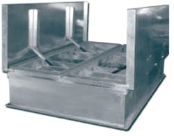
Typically, automatic vents are installed with curbs to protect them from the weather and to make them more visible to people walking on the roof (Photo A). Usually, the hatches are spring-loaded and released upon the melting of a temperature-rated fusible link.
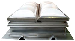
A dropout-type vent is shown in Photo B. The domes, which function as skylights, are made of a plastic that will melt and drop out at a prescribed temperature; no fusible link is involved. The vent can be opened manually from inside the building or from the roof. Typically, the panel sections are hinged. Like the automatic vent, the dropout vent is intended to be mounted on a curb.
Both types of vents rely on the effects of gravity to let hot smoke and gases out of a building.
UL and FM Global (insurer of industrial and storage facilities and successor organization to FM) have standards governing the design, construction, and operation of smoke and heat vents: UL 793, Automatically Operated Roof Vents for Smoke and Heat, and Class Number 4430, Approval Standard for Heat and Smoke Vents, respectively. Both standards address wind uplift, wind load, live load, impact testing, hail testing, fire exposure for dropout-type plastic domes, and fuse-link operational testing. UL, however, requires vents to be openable from both inside and outside a building; dome vents to pass an ultraviolet-light test; vents to operate automatically, independent of electrical power and other energy sources; and fusible links to withstand temperatures no greater than 286°F.
Vents in Unsprinklered Buildings
The current (2012) edition of NFPA 204 includes design criteria based on scientific principles of fire growth in unsprinklered buildings.
In determining needed vent area, NFPA 204 requires identification of the type of growth model—either "limited," whereby a fire grows to and remains at a maximum heat-release rate, or "continuous," whereby heat-release rate remains below its maximum level—to be employed. Design objectives (e.g., maximum smoke-layer height above the floor, maximum smoke-layer temperature) then are defined for a given period of time—typically, 20 min. If fire-department operations are not going to take effect until after that period, the vent ratio needs to be increased or the smoke layer lowered.
NFPA 204 identifies the following factors involved in the design of a venting system:
• Layout of curtained areas.
• Draft-curtain depth.
• Type of detector and specific characteristics.
• Detector spacing.
• Time following detection for clear area to be maintained below the smoke layer.
• Total vent area.
• Distribution of individual vents.
• Makeup-air inlet area.
NFPA 204 provides hand calculation methods for:
• Fire-growth rate.
• Estimated maximum fire size.
• Estimated fire duration.
• Mass consumed.
• Estimated fire-detection time.
• Smoke-layer temperature.
• Required vent area.
• Smoke-layer height vs. time.
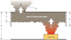
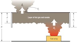
Basic design equations can be found in NFPA 204. Some of the parameters are represented in Figure 1, where H is building height, d is smoke-layer depth, dc is draft-curtain (or boundary-wall) depth, ṁp is mass flow from the fire, Av is vent area, and ṁv is mass flow through the vent. Annex A of NFPA 204 provides ample explanatory material, while Annex B provides the theoretical basis for LAVENT fire- and smoke-modeling software, and Annex D provides sample calculations for a vent system.
The ganged-vent concept, whereby all vents in a zone are arranged to open simultaneously upon the detection of smoke by a device, has been modeled, but not full-scale tested. A proposal to include it in NFPA 204 was rejected. The use of power may adversely affect the UL listing of vents arranged in a ganged manner.
Vents in Sprinklered Buildings
During the mid-1970s, following the addition of a requirement for smoke and heat vents in “unlimited-area” buildings to the Building Officials and Code Administrators International code, questions concerning the use of vents in sprinklered buildings began to arise. Not only was there concern about cost-effectiveness, there was concern about vents interfering with the efficacy of automatic sprinklers.
In FM tests of sprinklers operating alone, fire from burning rubber tires was controlled within 15 min. At 60 min, doors to the test facility were opened, and the fire escalated. At 94 min, 50 sprinklers were open; at 117 min, 94 were open. All together, 95 sprinklers operated. Upon closure of the doors, the oxygen level fell to 15 percent, and the fire subsided. In two later FM rack-storage tests conducted with vents, twice as much damage occurred and more than two times as many sprinklers operated than in tests conducted without vents.
Results of a 1974 FM study were similar, raising concerns about vents causing sprinkler systems to fail. In 1979, NFPA 1, Uniform Fire Code, prohibited vents in sprinklered buildings with high-pile storage.
In 1994, FM tests on retail-warehouse commodities showed detrimental effects when draft curtains were used. In 1998, The Fire Protection Research Foundation confirmed FM’s draft-curtain findings and concluded vents are unlikely to open if a sprinkler system is adequate or slightly inadequate for a hazard. No adverse effects were determined.
The current edition of NFPA 204 provides little direction in terms of the design of vent systems in sprinklered buildings. Chapter 11 states:
11.1: Where provided, the design of venting for sprinklered buildings shall be based on an engineering analysis acceptable to the AHJ (authority having jurisdiction), demonstrating that the established objectives are met.
Additionally, the appendix reads:
A11.1: Chapters 4 through 10 represent the state of technology of vent and draft curtain board design in the absence of sprinklers. A broadly accepted equivalent design basis for using sprinklers, vents, and curtain boards together for hazard control (e.g., life safety, property protection, water usage, obscuration) is currently not available. Designers are cautioned that the use of venting with automatic sprinklers is an area of ongoing research to determine its benefit and effect in conjunction with automatic suppression. See Section F.3 for more information.
This is vague and places a significant burden on designers and AHJ as to what to do.
Because of concern about vents interfering with the operation and effectiveness of sprinklers, the 2010 version of NFPA 13, Standard for the Installation of Sprinkler Systems, restricts the use of vents:
Section 12.1.1.1: Manually operated roof vents or automatic vents with operating elements that have a higher temperature classification than the automatic sprinklers shall be permitted.
Section 12.1.1.2: ESFR (early suppression fast response) sprinklers shall not be used in buildings with automatic heat or smoke vents unless the vents use a high-temperature rated, standard response operating mechanism.
The appendix note for Section A12.1.1 of the 2010 version of NFPA 13 states:
Sprinkler protection criteria are based on the assumption that roof vents and draft curtains are not being used.
The appendix note for Section C.6 of the 2010 version of NFPA 13 states:
Tests were conducted as a part of this program with eave line windows or louvers open to simulate smoke and heat venting. These tests opened 87.5 percent and 91 percent more sprinklers than did comparative tests without windows or louvers open.
... The design curves are based upon the absence of roof vents or draft curtains in the building. During mop-up operations, ventilating systems, where installed, should be capable of manual exhaust operations.
In Property Loss Prevention Data Sheet 2.0, FM Global publishes criteria for the use of vents in sprinklered buildings in part as follows:
2.1.1.7.1 Do not install automatic smoke and heat vents in facilities equipped with sprinkler protection; manual heat vents and smoke vents, however, are acceptable.
But FM Global recognizes that, until recently, many jurisdictions essentially mandated the use of vents:
If local codes require the installation of automatic smoke and heat vents, do one of the following:
• Install FM Approved vents for occupancies protected by QR (quick response) storage sprinklers
• Use standard response 360-degree F operating devices
• Install quick-response sprinklers directly under the vents on a max. 4 ft. spacing (16 sf)
• Install vents that are only manually operated
• Ganged vents require special provisions
• Mechanical systems should be manual only for operation after fire control is achieved
It is important to note that if the fusible-link operating mechanism of a gravity vent is 360°F, as recommended by FM Global, the vent no longer will comply with its UL listing.
The International Building Code (IBC) and the International Fire Code (IFC) mandate that vents be installed in most factory and storage buildings of more than 50,000 sq ft and in areas with high-piled (rack) storage of combustibles of more than 2,500 sq ft not protected by ESFR sprinklers. The IBC and IFC require automatic and manual operation and allow AHJ-approved mechanical alternatives. For mechanical exhaust systems, Section 910.4 of the IFC specifies 300 cfm of exhaust for each square foot of calculated vent area, maximum fan spacing of 100 ft, activation by sprinkler-waterflow or heat detector, protection of power wiring ahead of the main breaker for at least 15 min, and makeup sized at a minimum of 50 percent of exhaust located low in the space.
Exhaust rate, it has been noted, is based erroneously on criteria for non-sprinklered buildings, resulting in excessive numbers of air changes per hour. In any case, the mechanical-exhaust option is at a distinct disadvantage, requiring special approval, and appears to be inferior to traditional smoke and heat vents, which rely on gravity for smoke removal from a building. This is difficult in a building in which operating sprinklers would cool smoke. No criteria are proposed for the system’s approval.
Clearly, the criteria in these codes create a dilemma for design professionals: Installation standards caution against the use of vents in sprinklered buildings without providing a design basis, while building and fire codes mandate the use of vents in sprinklered buildings.
Potential Solution
In conjunction with the California State Fire Marshal’s office, the International Code Council's (ICC's) Code Technology Committee proposed a comprehensive change to the 2015 editions of the IBC and IFC, one allowing use of mechanical systems in factory and storage buildings on par with that of traditional gravity-type smoke and heat vents. This proposal was approved during a public hearing in April 2013 and will be subject to final approval during the ICC's 2013 Annual Conference and Expo in the fall. Major elements of the proposal include:
• The requirement of smoke exhaust for factory and storage buildings greater than 50,000 sq ft with high-piled storage.
• The equal treatment of vents and mechanical exhaust.
• The basing of vent area on volume (sprinklered buildings) or area ratio (unsprinklered buildings).
• The basing of mechanical exhaust on building volume (two air changes per hour).
• Maximum fan size, maximum spacing.
• The requirement of makeup air.
• Fans meeting minimum temperature criteria.
• The requirement of manual controls accessible from the exterior for fire-department use.
• Wiring ahead of the main breaker, similar to a fire pump.
• The protection of wiring with a thermal barrier.
• Maintenance provisions for vents and mechanical systems.
Properly designed mechanical systems will not be materially affected by sprinkler operation, wind, or inadvertent operation. Manual controls will allow fire responders to activate or stop an exhaust system at their discretion without the risk of a firefighter being on the roof of the building. These provisions, if adopted, will enable safer and more effective firefighting and provide a superior method of exhausting large buildings that have experienced fire.
Carl Baldassarra, PE, FSFPE, is executive vice president, western regional operations, for Rolf Jensen & Associates Inc., a global fire-protection consulting firm. He has a bachelor’s degree in fire-protection engineering from the Illinois Institute of Technology and a master’s degree in management from Lake Forest College.
Did you find this article useful? Send comments and suggestions to Executive Editor Scott Arnold at [email protected].


