


According to a Spanish proverb, it takes much silver to find gold. This saying holds true if what you seek is a Leadership in Energy and Environmental Design (LEED) Gold rating—except, in this case, the silver you invest is engineering expertise.
The May issue of HPAC Engineering contained an article on the U.S. Environmental Protection Agency’s (EPA’s) Region VII Science and Technology Center in Kansas City, Kan.,1 which was awarded LEED Gold certification in 2003. Gold certification is awarded to buildings that earn 39 to 51 points under the U.S. Green Building Council’s 69-point LEED rating system (www.usgbc.org/LEED).
The EPA’s only dioxin analysis laboratory, the Science and Technology Center features a laboratory fume-hood system utilizing variable-speed fans, heat-recovery coils, and high-quality fume hoods and control valves; chilled- and hot-water systems employing variable-speed pumping throughout; a chilled water system with a heat-recovery system that runs hot condenser water through a heat exchanger to provide hot water for dehumidification when required; and, for the administrative and office areas, a high-quality variable-air-volume (VAV) system with carbon-dioxide- (CO2-) controlled ventilation. All of this is controlled with an off-the-shelf control system running standard control algorithms.
The facility is controlled with a Web-based, native-BAC net building-automation system (BAS). High-speed, 32-bit controllers are used on the air-handling units (AHUs) and mechanical-room equipment, while 16-bit controllers are used on the VAV boxes. The building’s 10/100-mbps Ethernet forms the backbone of the control network, with 156- kbps Arcnet segments running to the field controllers. The fume-hood controllers run on a Modbus network and connect to the rest of the system through a Modbus-to-BACnet/Ethernet gateway. Hard-wired connections provide monitoring and alarming.
This article will describe energy-saving features involving administrative area VAV control and laboratory-ventilation control and discuss the integration of different systems and protocols into a single user interface.
ADMINISTRATIVE-AREA VAV CONTROL
The control algorithms were carefully designed to minimize energy use. For example, the administrative-area VAV-box controllers use a learning adaptive optimal-start routine with outside-air-temperature compensation to ensure the system is not turned on until the last possible moment in the morning. Rather than schedule the AHU that supplies these zones to start at a fixed time every morning, it waits until the optimal-start routine in one of its zones calls for cooling. On a cool, pleasant spring morning, the AHU may not start until workers arrive. On a hot, muggy August morning, however, the AHU may start a couple of hours earlier to make certain the building is cooled before workers arrive.
The temperature of the supply air coming from the AHU is similarly controlled by the cooling requirements of the zones. A set-point-optimization routine adjusts the AHU supply-air temperature based on the need for cooling in the zones. Whenever the proportional-integral-derivative (PID) loop in a zone calls for more than 80 percent of the maximum available cooling, the zone controller sends a cooling request to the AHU. The AHU, in turn, adjusts its supply-air set point between 55°F and 62°F, based on the number of zones requesting cooling. By carefully matching the start-up time and AHU supply-air temperature to the actual needs of the zones, the building provides a comfortable work environment while still meeting the LEED criteria. See the thermal-comfort floor plan in Figure 1. Any zone that is not red is within the comfort envelope.

In the administrative areas, considerable savings are possible through careful control of the outdoor-air dampers. An enthalpy economizer compares the enthalpy of the outdoor air with that of the return air to determine if free cooling is possible. When the enthalpy of the outdoor air is less, the mixed-air dampers modulate to provide mixed air at or slightly below the cooling set point to minimize energy used by the cooling coil. When the enthalpy of the outdoor air is greater, the dampers close to provide the minimum required ventilation. A request-based control scheme tells the AHU if the zones are occupied. If the zones are unoccupied, no ventilation is required. If they are occupied, the dampers open to provide a minimum 5-percent outdoor air. That this percentage is so low is because a CO2 control scheme will open the dampers farther if necessary.
CO2 in the return- and outdoor-air streams is monitored continuously. As long as the return-air CO2 is within 200 ppm of the outdoor-air level, the damper is allowed to remain at the 5-percent position. If the difference rises above 200 ppm, the damper opens farther, until it reaches 100-percent outdoor air at a difference of 1,000 ppm. In practice, the damper rarely needs to open beyond the 5-percent minimum, yielding significant energy savings.
LABORATORY VENTILATION CONTROL
Most of the square footage of the building is laboratory space. The nature of the work conducted in that space requires 100-percent outdoor-air ventilation 24 hr a day. Energy use is minimized by utilizing glycol-loop heat-recovery coils and by using a sophisticated variable-flow control strategy for the entire ventilation system.
Control of the energy-recovery loops (the green piping in Figure 2) in the laboratory- ventilation system was based on three modes:
Winter heating mode. If the outside-air temperature is less than the indoorair temperature, and the AHU is supplying heat, then a glycol coil absorbs heat from the exhaust air and uses it to preheat outdoor air entering the AHU. Because the laboratory requires 100-percent outdoor air, even a small temperature change can yield significant energy savings.

• Summer cooling mode. If the outside-air temperature is greater than the indoor-air temperature, and the AHU is supplying cooling, then exhaust air is used to cool a glycol coil, which precools outdoorair entering theAHU. Again, even a small temperature change can yield significant energy savings (Figure 2).
• Summer dehumidification mode. If the outside-air temperature is greater than the indoor-air temperature, and the supply-air humidity is high, a “runaround” loop may be employed. A humidity PID loop sets a low limit for the chilled-water control valve, so if the need for dehumidification is greater than the need for cooling, the valve will open far enough to keep the humidity below its upper limit. If this causes the supply air to fall more than 2°F below its set point, the system will activate the runaround loop to reheat the supply air. The glycol coil in the AHU outside-air duct is heated by the incoming air. This glycol then is pumped to a reheat coil downstream from the chilled-water coil, where a reheat PID loop modulates the flow to bring the return air back up to the desired temperature.
At the heart of the VAV laboratory-ventilation control are the laboratory fume hoods. These hoods are required to maintain a 100-fps face velocity, regardless of the position of the sash (a vertically sliding glass door). Thus, as the sash is raised or lowered, the fume-hood controls vary the amount of airflow exhausted through the hood to maintain 100-fps flow into the hood. This air is replaced by treated air flowing into the room through ceiling diffusers. This incoming air also is used to control temperature in the room. If the room is too warm, the temperature- control loop increases the amount of incoming air to cool the room. If the room is too cold, the loop will try to decrease the amount of incoming air. This amount cannot be reduced below that required to make up for the flow-hood exhaust; so, when the flow cannot be reduced any further, a reheat coil is used to warm the incoming air.
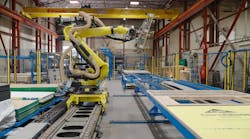
For containment purposes, the labs have to be maintained at a slight negative pressure at all times.This is accomplished with a separate room-exhaust system, which is controlled so that the total amount of air exhausted by the fume hood and room exhaust is 200-cfm more than the amount of supply air. The room-flow system, therefore, has to keep track of the air being exhausted by the fume hood and the temperature of the room, control the incoming air accordingly, control the exhaust air to maintain negative pressure, and control the reheat coil as necessary. When someone opens a fume hood, all airflows need to change immediately. The incoming air is supplied by a heating and cooling AHU with a variable-frequency-drive- (VFD-) controlled supply fan, while the exhaust air is routed through an independently controlled VFD exhaust fan. A control-system graphic is shown in Figure 3. A typical laboratory room is shown in Photo A.


As is the case with any modern building, a multitude of other systems affect energy use. The laboratory fume hoods are a major energy consumer. Four process chillers staged to provide chilled water upon request are controlled by the primary BAS. A stand-alone computer-room unit draws chilled water from the process chillers. All of these systems are integrated by the BAS into a single operator interface. The BAS also monitors non-energy-consuming systems, including fire, eye-wash, uninterruptible power, acid neutralization, bottled gas, and back-up generating. This provides a single interface to monitor and control the entire building. An idea of how seamless this interface is can be gained by comparing the BACnet controller in Figure 4 with the Modbus laboratory fume hood in Figure 3.
The laboratory fume-hood controller shown in Photo A uses the Modbus protocol and is integrated into the native-BACnet BAS through a BACnet/Modbus gateway. The office VAV controller shown in Figure 4 is directly linked to the BAS, as it is a native-BACnet controller. Regardless of the language used by the controller, the user has the same access to graphics, set points, thermographic colors, trends, schedules, alarms, and other user-interface features of the front end. The end result is that the building manager has a consistent interface and a consistent set of management tools to use throughout the system.

CONCLUSION
So, what does it take to earn a LEED Gold rating? First, it requires good equipment, as no system can outperform its components. Second, it requires good controls, as no system can outperform its “brain.” Most of all, it requires an intelligent designer, one who can look at the entire building and get all of the pieces to work together, eliminating unnecessary run time here, utilizing waste heat there, and generally exercising common sense. The good news is that a LEED Gold system does not have to be gold-plated. You need good, but not extravagant, controls and equipment. The better news is that a LEED Gold system will save energy and money over the long run. Spend a little silver now, and enjoy your gold for years to come.
REFERENCE
- Benton, D.J. (2004, May). EPA science & tech center good as gold. HPAC Engineering, pp. EGB14-EGB17, EGB21.
Steve Tom, PhD, PE, is director of technical information for Automated Logic Corp. He began working with pneumatic controls as an engineering trainee with Robertshaw Controls during the late 1960s, then spent 21 years in the U.S. Air Force, working with HVAC systems around the world and teaching courses on HVAC design and HVAC controls. He can be contacted at [email protected].