Minimizing Ammonia Charge in Industrial Refrigeration Systems, Part 1 of 2
Editor’s note: This article is adapted from the white paper “Low Ammonia Charge Refrigeration Systems for Cold Storage,” published by the International Association of Refrigerated Warehouses and the International Association for Cold Storage Construction.
From a pure technical and environmental perspective, ammonia (NH3) is unparalleled as a refrigerant. It is a natural refrigerant with no global-warming or ozone-depletion potential, its heat-transfer characteristics are among the best known to man, it is inexpensive, and its use for more than 100 years has led to a base of experience unlike that of any other refrigerant in the cold-storage and food-processing industries. In the hands of untrained or careless individuals or in poorly maintained facilities, however, it can be highly dangerous.
Over the last decade, NH3 has come under increased scrutiny from regulatory authorities, communities, and insurance providers, leading public-refrigerated-warehouse (PRW) owners to reach out to engineers, contractors, and equipment suppliers for new and innovative ways to minimize their NH3-system charges.
This article provides an overview of five alternatives to conventional pumped-recirculated-liquid (PRL) systems:
- Advanced direct expansion (also known as dry expansion or DX) utilizing electronic expansion valves.
- Carbon-dioxide (CO2)/NH3 cascade.
- CO2/NH3 with pumped volatile brine (PVB).
- A line of air- and water-cooled NH3 packaged chillers and a line of air-cooled condensing units.
- A line of self-contained refrigeration systems.
These systems fall into one of three general categories:
- Central, meaning they are used to minimize or eliminate unused NH3 charge.
- Hybrid, meaning they are used to confine NH3 charge to the machine room and use a second coolant in cold rooms.
- Packaged, meaning they eliminate interconnecting piping and corresponding NH3 inventory with numerous smaller, self-contained systems.
Central System
Advanced DX
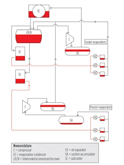
A properly designed DX system utilizes fewer vessels and fewer and smaller-diameter pipes and does not require pumps. The key difference between it and a pumped NH3 system is that the high-pressure liquid in a DX system is fed directly to each evaporator via an expansion device at the evaporator inlet. The heat-transfer objective of the evaporator is to vaporize all of the liquid before it leaves the evaporator.
Figure 1 shows the fundamentals of a DX system.
Special considerations of advanced DX systems include:
- Water removal. While water is detrimental to evaporator performance in any type of NH3 refrigeration system, it is particularly troublesome in DX systems. Not only does it raise the boiling point of NH3, it presents a false picture of superheat from a control-system perspective. To prevent problems associated with water, installation of a water-still/removal device is recommended.
- Subcooling. Subcooling liquid eliminates the formation of unwanted vapor in liquid lines, which can be detrimental to the performance of expansion devices and coils.
- Electronic expansion devices. There are two basic types of electronic expansion valves suitable for NH3 applications: pulse-width modulating (PWM) and motorized. For coil applications, either is suitable, although the PWM valve has some limitations with respect to minimum required pressure differential. What is most important is an expansion valve’s ability to respond as fast as required by a controller.
- Controls and variable-frequency drives (VFDs). The use of advanced control algorithms is essential to ensuring liquid is metered to coil circuits in such a way that evaporator performance is optimized. At the same time, the control system must be able to provide a high level of assurance that little or no refrigerant liquid is carried over to the suction accumulator vessel. For controls to perform reliably, steps should be taken to avoid sudden, dramatic changes in suction pressure and/or discharge pressure. The most effective means is to employ VFDs on condenser fans and compressors.
Jeff Welch estimated the NH3 charges of a pumped system and an equivalent DX system.1 The DX system had an NH3 charge of 6,053 lb. On a per-ton basis, that translates to roughly 8 lb of NH3 per ton of refrigeration (TR), or about 40 percent of the charge of an optimized pumped system. The design of an all-DX facility in the Midwest similar to the hypothetical system resulted in an NH3 charge of approximately 7.5 lb per TR.
With a DX system, compressor suction pressure will be lower than it will with a pumped system because of the formation of superheat in the evaporator; with today’s advanced controls, however, superheat can be decreased significantly. Discharge pressure will be similar; with electronic expansion valves, it can be reduced when the opportunity arises. Condenser- and evaporator-fan horsepower also will be similar. The lack of recirculator pumps will result in a slight energy savings with a DX system; while there may be a penalty for subcooling, it likely will be insignificant. The conclusion that can be drawn from all of this is that there are no significant differences in energy consumption between a DX system and a pumped system—with one exception: Because of the significantly lower liquid charge in the evaporators and top-feed evaporators of the DX system, pump-out time for hot-gas defrost should be dramatically less. Energy is saved as a result of shorter defrost cycles and reduced heat input during defrost.
Bruce Nelson estimates defrost-cycle-associated savings alone can range from $12,000 to $26,000 per hundred TR per year.2 Conservatively, the energy use of a DX system is an estimated 2.5 KW per TR.
In a comparison of an actual DX system with an equivalent pumped system, the cost of the DX system was $6,920 per TR, or about 97 percent of the cost of the pumped system.
While a DX system has oil stills and anhydrators that must be maintained, there will be far less oil to drain throughout the system (as less oil is carried to the evaporators as a result of the oil stills) and no refrigerant pumps to maintain. For the purpose of this analysis, then, there is no significant difference in maintenance cost between a DX system and a pumped system.
Hybrid Systems
CO2/NH3 cascade
Recent advances in materials, manufacturing, equipment design, and controls have made CO2 a highly viable alternative to many of the more common refrigerants and heat-transfer fluids used in industrial refrigeration systems. There are several variations in CO2 refrigeration, including compressed CO2 for the room side, with NH3 serving as the initial heat sink (condenser) for the CO2 process.
As with all refrigerants, the higher the temperature, the higher the operating pressure. The NH3 part of a CO2/NH3 cascade system provides the initial condensing for the CO2 part and, thus, limits the pressure that would exist if CO2 were condensed as in a typical refrigeration cycle (95°F condensing temperature, typically). The evaporator for the NH3 system is the condenser for the CO2 system. This is referred to as a cascade heat exchanger and can be constructed in a number of ways:
- Shell and tube.
- Welded plate.
- Shell and plate.
The choice of style will have a direct impact on the refrigerant charge of a system, with shell and tube requiring the most refrigerant and welded plate requiring the least.
There are several approaches to achieving desired temperatures of coolers and freezers. For this configuration:
- Cool the CO2 to the temperature required by the coolers through the cascade heat exchanger and send it to the CO2 recirculator vessel.
- Pump some of the condensed CO2 from the cascade heat exchanger to the cooler coils. Supply additional liquid from the CO2 recirculator to the freezer coils.
- Return the gas/liquid mixture from the cooler coils and freezer coils to the CO2 recirculator.
- Send the vapor collected in the recirculator back to the CO2 compressor, compress it, and send it to the cascade heat exchanger to be condensed, while the liquid is circulated back to the coolers and freezers.
The system is relatively simple and does not require much more equipment than a two-stage PRL system does. Advantages of CO2 as a refrigerant arise from its high heat-transfer coefficient at very low temperatures and favorable vapor-to-liquid volumetric ratios. This leads to:
- A more efficient cascade heat exchanger (reduced energy consumption attributed to a lower temperature-difference requirement).
- Smaller evaporators.
- Lower recirculation rates.
- Smaller pumps.
- Reduced pumping power demand.
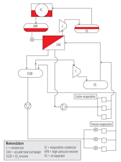
As can be seen in Figure 2, all NH3 is confined to equipment residing in the machine room.
Special considerations associated with the use of CO2 as a refrigerant include:
- Excessive pressure rise resulting from the transfer of heat from the ambient environment when power is disconnected from the system, a period known as “standstill.” The simplest solution is to install a small generator-driven condensing unit to condense any vaporized CO2 within the system.
- The negative impact of water on CO2 evaporators and, under certain circumstances, other system components. The problems associated with water in CO2 systems are directly related to CO2’s low solubility limit. Once the limit has been reached—especially when temperatures are below freezing—carbonic acid can form and be highly detrimental to carbon-steel components. The solution is to install filter dryers in liquid lines prior to evaporators.
- Oil must be kept in the part of the system where it is required (the compressor) and not be allowed to migrate to low-temperature parts of the system. The use of an oil “still” or something equivalent is strongly recommended.
- Although CO2 is non-toxic and non-flammable, it is heavier than air and, thus, sinks to the floor. This can result in non-breathable air in confined spaces. Leak-detection and emergency ventilation systems are essential.
- The interaction between CO2 and oil. There are two types of oil for compressed CO2 systems: polyalphaolefin (PAO) and polyolester (POE). In general, both have positive and negative attributes when it comes to their interaction with CO2. In the case of POE, the only real negative is its affinity to water. To ensure the long-term stability of POE, a system should be kept as water-free as possible. Again, filter dryers will accomplish this objective.
While the NH3 charge in a CO2/NH3 cascade system is estimated to be as much as 90-percent less than that in a typical PRL system, data suggest the difference is not nearly as great in reality. United States Cold Storage (USCS) has seven CO2/NH3 cascade facilities in operation and two more under construction. The typical NH3 charge in these facilities is approximately 8 lb per TR; the theoretical value for CO2/NH3 cascade facilities is 4 to 6 lb per TR. It is clear that while 4 lb per TR is achievable, it may not be a particularly practical objective. For the purposes of this article, the charge in CO2/NH3 cascade facilities is conservatively estimated to be 6 lb per TR.
USCS estimates its average power consumption is 1.8 to 2.0 KW per TR. This value, however, is based on design loads and measured kilowatt-hours. In general, USCS refrigeration loads are fairly heavy on blast freezing. CO2 is particularly energy-efficient at temperatures below -30°F. Additionally, because this is an aggregate value for seven facilities, it is likely actual condensing temperatures are well below 95°F. This would have the effect of lowering the KW-per-TR ratio. The general conclusion is that the true ratios probably are higher than those estimated by USCS; however, the values project numbers that fall within the broad range anticipated for this type of system. There is strong evidence3 facilities with blast freezers exhibit significant improvements in energy consumption when using CO2/NH3 cascade systems. The cascade system exploits the best efficiencies of NH3 and CO2 compressors: NH3 compressors have higher efficiencies at higher temperatures; CO2 compressors have higher efficiencies at lower temperatures. The optimum temperatures for this efficiency improvement typically are lower than -30°F.
The value for the system in a Pacific Gas & Electric Co. study3 was 2.3 KW per TR. Assuming a small decrease in efficiency at a 95˚F condensing temperature, the value for this system will be set at 2.4 KW per TR. Taking into account the amount of theoretical work that has been undertaken to compare systems, it is prudent to use a value not less than that for a PRL system. For the purposes of this article, the value will be set at 2.5 KW per TR.
One of the highly beneficial characteristics of CO2 compared with NH3 is smaller-diameter pipe for carrying vapor. (Although lines for CO2 liquid typically are larger than those for NH3 liquid, they still fall into the small-diameter category.) Smaller pipe diameter translates to savings in:
- Materials.
- Transportation.
- Welding.
- Painting (if applicable).
- Insulation.
From an installation perspective, a CO2/NH3 cascade system can be more cost-effective than a PRL system. USCS determined the average installed cost of its CO2/NH3 cascade systems was at the low end of the scale for all installed systems. This might be attributed to economies of scale, as USCS facilities usually are quite large, or perhaps favorable locations with respect to building costs and/or other factors. Refrigeration contractors, on the other hand, have painted a somewhat different picture. While the cost of a CO2/NH3 system is not significantly higher than that of a PRL system, three very large contractors who have both quoted and built CO2/NH3 facilities stated a CO2/NH3 cascade system carries a slight premium in cost compared with a PRL system. For the purposes of this article, it will be assumed there is a premium of 5 percent, or $7,400 per TR, in installed cost over the baseline system.
In terms of maintenance costs, there is not a great deal of difference between a CO2/NH3 cascade system and a conventional PRL system. A reliable maintenance staff following a sound maintenance plan should have no problem meeting the special requirements of filter-dryer and oil- and water-still maintenance with little increase in cost. The conclusion here is that while maintenance costs may be higher with a CO2/NH3 cascade system, they will be only minimally so.
References
- Welch, J. (2013). DX evaporator installation – Final project report. Retrieved from http://bit.ly/Welch_DX
- Nelson, B.I. (2013). DX ammonia piping handbook. Colmac Coil Manufacturing. Retrieved from http://bit.ly/Nelson_DX
- PG&E. (2009). Cascade C02/NH3 refrigeration system efficiency study. PGE 0707. Emerging Technologies Coordinating Council.
Next month, Part 2 of this article will discuss a second hybrid system, CO2/NH3 with PVB, as well as three types of packaged systems: an air- and water-cooled NH3 packaged chiller, an air-cooled condensing unit, and a self-contained refrigeration system.
National business-development manager for Danfoss Industrial Refrigeration, Terry L. Chapp, PE, has been involved in all aspects of HVACR, with particular emphasis on heat exchangers, valves, and controls, over the last 35 years. He is a member of The American Society of Mechanical Engineers, ASHRAE, the International Institute of Ammonia Refrigeration (IIAR), and the Refrigerating Engineers and Technicians Association. He serves on the safety committee of IIAR and the refrigeration and engineering committee of the Global Cold Chain Alliance.
Did you find this article useful? Send comments and suggestions to Executive Editor Scott Arnold at [email protected].