Lunching and Learning: A Civil Engineer’s View of a Campus Chilled-Water System

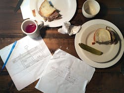
Fred, a mechanical engineer, was bursting to tell William, a civil engineer, all about his design for a new campus chilled-water system. They had been friends for years and met weekly for lunch at their favorite restaurant.
“So,” William said after listening to Fred describe the system, “let me get this straight: You are designing a system to feed chilled water to the entire campus, and it is different from other systems because it is ‘buffered.’ The buffering is accomplished by a stratified tank that stores chilled water to let it be used later in the hour or day. I have heard of storage of chilled water in stratified tanks to reduce daily demand charges. Is that what this is about?”
“No,” Fred replied. “This is done on a much smaller scale with a different goal in mind. This stratified buffer tank does not store a day’s worth of chilled water. It stores only enough for the smallest chiller in the system to run and turn off. That way, a chiller can run at its most efficient KW-per-ton point every hour it operates. The chiller turns on, makes chilled water as efficiently as it can, and turns off. The attached chilled-water loads continue to consume chilled water from the tank when the chiller is off. When more chilled water is needed, the small chiller starts again. Our particular system has an instantaneous capacity of 5,000 tons. We will serve that load with two 2,000-ton chillers, three 500-ton chillers, and two 200-ton chillers. We have extra capacity for some redundancy. So, if the current load is 1,100 tons, two 500-ton chillers will operate continuously, and one of the 200-ton chillers will cycle on and off to handle the rest of the load for 30 min each hour.”
“Interesting,” William said. “Tell me more about the load on the system. What kind of a daily load in gallons per day or similar measurement do you have for the campus?”
Fred responded: “Our daily load measurement is in ton-hours per day, which is similar to your gallons per day. Most chilled-water systems are designed for the peak instantaneous load of the system in tons without ever knowing the ton-hours. As I said, our peak instantaneous load is around 5,000 tons. However, in this particular instance, I can answer your question about daily load because the owner wanted us to look into using a stratified chilled-water storage tank that would be sized to reduce the KW demand between 10 a.m. and 10 p.m. to minimize demand charges. We predict the maximum load for that period to be a little over 20,000 ton-hours. This type of a stratified chilled-water storage tank would let us shift the production of chilled water to nighttime hours, when electrical demand and, sometimes, energy rates are lower. It is then stored in the tank to be used during the peak consumption period during the day. Producing chilled water at night to offset daily loads can save a lot of operating cost, but this comes at a very high first cost and with operating costs of its own. Oftentimes, these tanks can be over 1 million gal. Tanks that size are not built to be a pressure vessel, so complex pumping and valving schemes are needed to charge and discharge these tanks.1 This increases the energy consumption of these systems.”
“We size our systems on the daily load, not the peak hourly demand,” William said, “but we do allow our production systems to run all day and use elevated storage tanks to flatten out the demand on the system. Do you produce all the chilled water in one place?”
“Yes,” Fred replied. “We will have a chilled-water plant at the north end of campus. We are using a 16-degree delta-T between the supply- and return-water temperatures in the system, so we should only have to distribute a maximum of 7,500 gpm. We are reserving some space in this plant for future chillers and are oversizing our mains to allow future expansion of the campus chilled-water system.”
“Do you have any critical loads on this system?” William asked.
“Oh yes,” Fred answered. “The main computers for the whole campus will be cooled by our system. We have redundant chillers and pumps and can handle about 80 percent of the maximum campus load with the largest one of our main chillers and one of our campus distribution pumps down.”
“Tell me about the stratified buffer tank,” William requested. “It sounds similar to the water towers we use for domestic-water storage.”
“It is,” Fred said, “but stratified tanks store a temperature differential, rather than a volume of water. The fact that we are only storing enough chilled water to allow our smallest chiller to turn on and off means that our tank size is significantly smaller than the 1-million-plus-gal. tank needed for demand limiting. Our stratified buffer tank is in the 10,000-to-12,000-gal. range. This allows our stratified tank to be an ASME-rated pressure vessel, simplifying the whole system. Our stratified buffer tank will still have cold water stored in the bottom with warmer water at the top. As with stratified tanks, special manifolds distribute the water at very low velocities to avoid mixing hot water from the top of the tank with cold water in the bottom as cold water is being replaced with hot water when the consumption exceeds production. The same manifolds also avoid mixing the hot and cold water as the tank is charged when production exceeds consumption.
“This system lets us solve a sticky problem about chilled-water production that has been around for a long time,” Fred continued. “That problem is that the flow of water that a chiller can process is fixed or is most efficiently produced within a narrow range, but the variation of the chilled-water load is almost infinite. This difference in load and flow had to be dealt with while always maintaining the cold supply-water temperature. The previous solutions to this problem have all included bypassing some of the processed—chilled—water into the used—warm—water return for all but a very few hours, when the consumption of chilled water exactly matched the production of chilled water. That artificially made the flow on the load side the same as on the supply side while lowering the temperature of the water entering the chiller. For a specific load, lowering the entering-water temperature of a chiller lowers the chiller’s efficiency. It is sad really. There are a lot of campus systems that are quite draconian in enforcing a 14- or 16-degree delta-T from the buildings on the system. Some reduce the flow of supply chilled water into a building until the return water coming out of the building is warm enough. But because of the amount of bypass that is needed to match the production and consumption flows, the entering-water temperature of their chillers is still quite low.
“It doesn’t matter if you were doing a primary-secondary system or a variable-primary system,” Fred added. “The water entering the chiller was colder than what was coming back from the load for much of the year. Using the stratified buffer tank to replace and eliminate the bypass line solves that problem. The water entering the chillers is always as warm as what is returning from the buildings. Let me show you what I mean.”
Fred took a pen from the breast pocket of his shirt and sketched the system on a napkin (Figure 1).
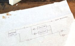
“When the operating-chiller capacity is lower than the building consumption, the pumps here remove the water from the bottom of the storage tank and force it through the piping system serving buildings on campus and out to the computer-lab building on the far end of the campus,” Fred explained. “The chilled water then goes through control valves and coils at each building and then goes back to the top of the storage tank. When the operating-chiller capacity is larger than the building consumption, the chiller pumps pull water from the top of the chilled-water storage tank, cool it in a chiller, and send it back to the bottom of the chilled-water storage tank. Our new system operates chillers independent of the instantaneous load of the buildings. Chillers are operated based on the average load. We no longer need to mix chilled-water supply water into the return just to make sure the supply is cold or to maintain a minimum flow on a chiller. Any difference in flow between the chillers and the buildings is made up by the stratified buffer tank.”
Fred continued: “As it turned out, a large chilled-water storage tank sized for the worst-day ton-hours load was way too expensive to pay for itself in a reasonable amount of time. A much smaller stratified buffer tank could still be used to decouple building loads from production and increase the overall efficiency of the system. We have sensors in the stratified buffer tank that show how much cold water is in the tank. When the tank is getting close to fully charged, a chiller is shut off. When the tank is getting close to fully discharged, a chiller is started. That allows chillers to cycle on an off during the day to match chiller capacity for the day to total load for the day. Turning a chiller off is more efficient than running it at a low load. Selecting a chiller without a variable-frequency drive reduces the chiller KW per ton at the design load. Right now, we are looking into what the optimal size for the stratified buffer tank will be. It will end up being sized on the minimum run time of the smallest chiller in our plant plus some safety factor.”
“Impressive,” William replied. “Tell me more about how you distribute all that water.”
“All our campus pumps are centralized in one spot, and they are manifolded together,” Fred said. “We can bring on pumps as needed to maintain a pressure differential between the chilled-water supply and return mains at the farthest building.”
Just then, lunch arrived. As they ate, Fred could tell William was thinking. When they finished, William pulled the sketch of the system closer.
“There are a lot of similarities between your campus chilled-water system and city water systems that I have been designing for years,” William said. “Both have pumps, both have production areas—water treatment and chillers—and both have storage tanks. City water systems start out small and have to grow with the town, and they have to be very reliable. One thing that jumped out at me right away when you were talking about reliability for the chilled water for the computer lab is that, if you had a failure of a piece of pipe between your chilled-water plant and the computer lab, there would be no cooling for the computer lab for quite some time. I have a suggestion about how to handle that, but the solution requires another twist in the approach.
“First, let me tell you a little bit about the city water system,” William continued. “Pressure is something that we see as a necessary evil. We have a pretty narrow band of pressure that is acceptable for the homes and businesses we serve. That pressure band is between 40 and 80 psi. We try to maintain that pressure band in long pipes. The pressure drop of piping and normal expansions to the system force us to have many water-treatment production facilities—similar to chillers—and many storage tanks because of the narrow band of pressures we have to maintain. The water system develops as a grid as the town street grid develops. With a lot of valves, the grid becomes very resistant to outages when a single pipe breaks.
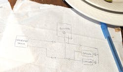
“So, here are my suggestions,” William offered. “Delete the campus pumps in favor of pumps at each building, and move the stratified buffer storage tank to what is currently the far end of the system. This will allow you to create a grid distribution system for your chilled water.”
William reached for his napkin and began sketching (Figure 2).
“The pressure drop of long pipes is something I know well,” he said. “We would never be able to pump a whole city from one location because of the pressures that would be required, and the transport energy would be ridiculous. Yes, I know that large pumps, in general, are more efficient than small pumps, but do the math and make some pump selections. Look at a building 2,000 ft away from the chilled-water plant with a small high-pressure drop load. You will see that the horsepower of the single pump at the plant will be more than the total horsepower of the building pumps.2 I am sure that you will also have some screaming control valves in buildings close to the plant, if you pump everything from the plant. Those control valves are wasting a lot of energy every hour the pumps are operating.
“I have designed a lot of pumps, so I must also point out that even though you would have your manifolded pumps on VFDs, there is a low limit to the gpm of those main pumps,” William continued. “Somewhere, there will have to be a bypass from the supply to the return for that minimum flow, allowing the big problem you mentioned before to keep haunting you by putting cold water in the top of your stratified buffer tank. Yes, pumps in the buildings will have VFDs and will need bypasses, too, but those can be set up to not affect your stratified-buffer-tank charge.
“Just put a pump at each chiller sized to get the water through the chiller, through the pipe, and through the chilled-water tank and back again,” William added. “No control valve is needed on each chiller as long as you have a check valve on the outlet of the pump. Eliminating control valves saves a lot of cost.
“Now, since the pumps are in the buildings, the stratified buffer tank can move,” William explained. “I would suggest you put it at the far south end of the system. Yes, I know it adds head to the chiller pumps, but it smooths out effects of starting up a second or third chiller on the chilled-water temperature. It also reduces the head needed at the building pumps, as the tank acts as a second source of chilled water when it is discharging. It also plays into this ....”
William turned over his napkin and began sketching (Figure 3).
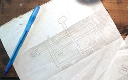
“Use a grid for your campus chilled-water distribution similar to a domestic-water distribution system,” William said. “Visualize it as chilled-water mains under the streets or sidewalks between buildings on campus with valves at junctions. Multiple paths for the chilled water will make the piping system more resistant to failure. One pipe break can be worked around quickly while maintaining service. Because sections can be valved off and modified without taking the whole system down, system expansions are relatively painless.
“I know you said you were oversizing your mains for future expansion, but knowing where that expansion will be is a very slippery thing,” William continued. “You have been around long enough to know that things that are planned to be built aren’t, and new needs create new buildings in awkward spots. The grid distribution system is more flexible. Water can flow either way in a pipe as needed to serve the loads.
“Space for future chillers does not need to be added at the plant you are designing,” William concluded, “and the mains only need to be sized for the current capacity of the chiller plant. Downsize the chilled-water plant for an option on another plant in the future on the east or the west or south. This will reduce first cost and make you a hero with the owner. The chilled-water system can be enlarged as future building plans are finalized by adding another chiller plant or adding to the grid. You never put yourself in the position of trying to explain to the owner that the piping installed just two or three years ago must be replaced with bigger pipes because the load has increased and the campus chilled-water system will be down for a month while this happens.”
Now, it was Fred’s turn to think.
“William, I always like having lunch with you. See you next week?”
“Sure.”
Editor's note: What do you think of the format of this article? Would you like to see more articles like this? If you were sitting at the table next to Fred and William and overheard their conversation, would you have something to add? If you would, what? Let us know in the comments section below.
References
1) Peterson, K.W. (2015, February). Engineer’s notebook: Chilled water TES hydraulics. ASHRAE Journal, pp. 40-43.
2) Taylor, S.T. (2011, July). Optimizing design and control of chilled water plants part 1: Chilled water distribution system selection. ASHRAE Journal, pp. 14-25.
Jeffrey Newcomb, PE, MBA, LEED AP, has been contemplating unusual HVAC systems as a consulting engineer for over 34 years. He works at IEFM Consulting Engineers in Coal Valley, Ill., where he is responsible for project management and design. He has degrees from the University of Illinois and The University of Iowa.
Did you find this article useful? Send comments and suggestions to Executive Editor Scott Arnold at [email protected].
About the Author
JEFFREY NEWCOMB
Jeffrey Newcomb, PE, MBA, LEED AP, has been contemplating unusual HVAC systems as a consulting engineer for over 36 years. He works for IEFM Consulting Engineers in Coal Valley, Ill., for which he is responsible for project management and design. He has degrees from the University of Illinois and The University of Iowa.